Notice. New forum software under development. It's going to miss a few functions and look a bit ugly for a while, but I'm working on it full time now as the old forum was too unstable. Couple days, all good. If you notice any issues, please contact me.
KarlJ Guru Joined: 19/05/2008 Location: AustraliaPosts: 1178
Posted: 10:55am 21 Jan 2010
Copy link to clipboard
Print this post
I've been considering the possible combinations of wiring 8x12v Batteries for 48V, I can parallel four pairs and then series the 4 to get 48V or just series four cells and then parallel each string.
I have read float voltage is just 2.27V giving 54.48V at the float charge level, now the inverter kicks in at 54V meaning almost regardless of bank size, there is almost no scope for a voltage rise.
This beggs the question what voltage do i kick in the dump load? 55V, 56V?
How much volt drop will I get when the dump load kicks in
at 1000W
batts are 80Ah each giving me 160Ah total capacity at 54V
if the dump kicks in will the inverter shut down thinking there is insufficient input power?Luck favours the well prepared
GWatPE Senior Member Joined: 01/09/2006 Location: AustraliaPosts: 2127
Posted: 11:25am 21 Jan 2010
Copy link to clipboard
Print this post
Hi Karl,
I assume you are quoting numbers for a Latronics PVE1200 ??
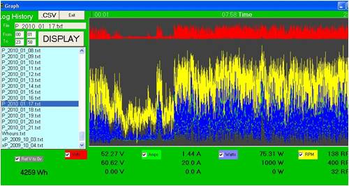
Here is some data from my own system.
This was from a reasonably good day, with > 4kWhr back to the grid.
The max power was about 800W, and the max battery voltage was 60.62V. The windmill/battery protection is set for approx 62V. The inverter is good up to 100V input. The battery/wiring at the up to 16A gives the spikes in the voltage graph. Grid connection was maintained and there was no dumping. If the windmill is shut down, then the inverter still maintains connection for up to 15min.
If yours is some other system then you need to explain some more.
Gordon.
become more energy aware
Tinker Guru Joined: 07/11/2007 Location: AustraliaPosts: 1904
Posted: 02:26pm 21 Jan 2010
Copy link to clipboard
Print this post
Karl, are you planning to connect the dump load at the same time your windmill output is still connected to the battery?
If so, I found that that is not a good idea , even with my small set up the dump load gets rather hot.
Now I have a relay that disconnects the battery while dumping (a changeover contact arrangement).
Once your battery disconnects from the mill during load dumping there is no battery voltage drop to worry about.Klaus
GWatPE Senior Member Joined: 01/09/2006 Location: AustraliaPosts: 2127
Posted: 10:12pm 21 Jan 2010
Copy link to clipboard
Print this post
A better solution is to run the dump load from a separate set of rectifiers from the mill AC. There can be no discharge of the battery this way.
Gordon.become more energy aware
Downwind Guru Joined: 09/09/2009 Location: AustraliaPosts: 2333
Posted: 01:41am 22 Jan 2010
Copy link to clipboard
Print this post
By the look in the photos of Karls cable run his rectifier was at the mill and only 2 dc cables run to the battery.
If this is the case than Tinkers method would be the better choice.
Pete.Sometimes it just works
GWatPE Senior Member Joined: 01/09/2006 Location: AustraliaPosts: 2127
Posted: 01:49am 22 Jan 2010
Copy link to clipboard
Print this post
If DC is only available, then a diode in the positive line, and the dumpload across the mill side of the diode will still work. The diode should be low forward voltage drop. Still doable, but slightly more loss on a low voltage system as the diode has to be rated for the max mill current.
Gordon.
become more energy aware
KarlJ Guru Joined: 19/05/2008 Location: AustraliaPosts: 1178
Posted: 09:00am 22 Jan 2010
Copy link to clipboard
Print this post
Sorry for the sarcasm but...
Tell me again why I paid $300 for a PL20 to do this
for me?
Interestingly enough they recommend against using a Diode but if I did it would obviously need to handle 20A give or take. Would a normal rectifier type do the trick? (rated for 35A.Luck favours the well prepared
Tinker Guru Joined: 07/11/2007 Location: AustraliaPosts: 1904
Posted: 02:22pm 22 Jan 2010
Copy link to clipboard
Print this post
Karl, I do not know much about your PL20 so I googled it:
http://www.plasmatronics.com.au/downloads/PLTypicalInstallIn fo.V1.11.pdf
It appears to be a solar regulator and regulates the negative side of the battery connection.
Since dump loads are normally associated with wind generators, are you trying to use this device for your wind mill??
P.S. I have since read your post in the windmill section and see they do have a windmill provision for the PL20.
What I do not understand is why they even bother to show a diagram without the diode.
You could try a 25A bridge rectifier with the 2 diodes to the positive post in parallel. If its a metal backed bridge its easy to fit a heat sink.
Edited by Tinker 2010-01-24Klaus
KarlJ Guru Joined: 19/05/2008 Location: AustraliaPosts: 1178
Posted: 10:26pm 22 Jan 2010
Copy link to clipboard
Print this post
I think they show the diagram without the diode as the PL20 does the switching through earth of the Dump load,
hence I cant see why its required.
Putting another diode in the mill output as shown in the PL20 wiring diagram, seems to serve no purpose other than keeping fingers warm on a cold day.Luck favours the well prepared


 , even with my small set up the dump load gets rather hot.
