
|
|
Forum Index : Electronics : WINDING COILS
| Author | Message | ||||
Greenbelt Guru Joined: 11/01/2009 Location: United StatesPosts: 566 |
MacGyver; I have been thinking about your project, Here is something Important. (100,000,000 Lines of magnetic force cut per second (per turn) of wire = 1 Volt), Take 1/2 this amount 50,000,000 using 2 Turns of wire, still = 1 Volt. To carry on-- If you have 10, million lines of force you would need 10 turns of wire cutting these lines (in one second) for 1 Volt., and finally if this 10 turn coil cut the mag field at the rate of 10 times a second, this would be 10 Volts. The above Says, Volts = strength of field,Multiplied by turns of wire, and this result is multiplied by speed or number of the passing magnets in one second. It can be seen that The speed of cut has a great influence on the output. The F&P works well because of many magnets, (cuts per revolution) and a large Circumference, which translates into higher magnet speed. I'm surprised that no one has mounted a stator ring at the blade tip to suck up the milliwatt's in low wind,! Southern cross Mod. anyone)? Yea I Know , now the windmill won't start up. See my post In windmills on a faster VAWT. Just an Idea . Assume the Stator contains only the 1- above described coil . 10 turns. And we assume the mag's all have the same flux value.Say 30 thousand lines. the Rotor is turning at 120 rpm. Now the Numbers,, 30 thousand lines x 10 turns = 300 thousand,, 120 rpm = 2 turns per second, 2 -TPS X 24 mags = 48 times per second the field cuts the turns of the coil . so 48 X 300,000 = 14,400,000 still need 85 million 600 thousand to generate a Volt. If we double the turns on the coil to 20 and all else remains the same here' s what happens. 30,000 X 20 turns = 600 thousand X 48 cuts per second = 28,800,000,, Nope, gotta have 185 turns at 30,000, Flux density, This = 5 million 550 thousand ,X double the speed to 240 rpm = 96 cuts per second =532800000 / 100,000,000= 5.328 volts. X 3 coils in series = 15.984 volts. (Edit; There is 24 mags and 9 coils total. The Knapp coefficient and impedance has not been calculated. End Edit) At 500 Rpm Voltage is 33.3. Efficiency at 70 % = 300 RPM at 14.2 volts.so each coil gets 15 more turns to cover losses. or better, get stronger mag's. Should add a cap. across the output diode to catch the peak volts to enhance the average voltage. SOME OF THE ABOVE MAY BE TRUE. Note; the force of your mags may be more or less than the number used. I can't remember the maxwells, orsteads, or, It may be Gilbert's� Faraday�s law �� Lenz's law � or henry's equivalent-for flux lines. manufacturer will have Info on the flux value. Another note; The stronger magnet = less wire, less resistance less space less speed and more product Time has proven that I am blind to the Obvious, some of the above may be True? |
||||
oztules Guru Joined: 26/07/2007 Location: AustraliaPosts: 1686 |
Yikes!..... no wonder I just wind a test coil 
The formula's and calcs may well be right.... but the minute you start to hook up to the battery..... it all falls to pieces. For an F&P your synchronous impedance will dictate what happens after startup. For an axial, it will be the R of the phases. The moment we achieve startup voltage, the above does not apply as a means of guessing the working coil voltage in an F&P or even the coil EMF (armature reactance will effect this). For an axial, we can at least subtract the E lost via R This inturn effects the efficiency. [quote]At 500 Rpm Voltage is 33.3. Efficiency at 70 % = 300 RPM at 14.2 volts.so each coil gets 15 more turns to cover losses. or better, get stronger mag's [/quote] Not sure how you effect the calculation on efficiency without knowing the stator impedance and the load impedance... or for an axial, at least the stator resistance and guess the batts as about zero impedance... from that you can get current and establish the efficiencies I guess,,, plus iron losses in the F&P The volts lost in the stator x the current will give you your losses ( or E^2/R ) ..... from there you can work out efficiency for an axial. [quote]Another note; The stronger magnet = less wire, less resistance less space less speed and more product[/quote] Stronger magnet allows less turns for the same rpm's per volt. To take advantage, we want to use the same space with the same mass of copper.... then we really win. ...........oztules Village idiot...or... just another hack out of his depth |
||||
KarlJ Guru Joined: 19/05/2008 Location: AustraliaPosts: 1178 |
dont know whether to  or or 
makes the f&p look easy, none of that to worry about Luck favours the well prepared |
||||
| GWatPE Senior Member Joined: 01/09/2006 Location: AustraliaPosts: 2127 |
Hi oztules, I have to agree about winding a test coil. This is really the best way to confirm a magnet configuration. The simulator "sparweb" found is a useful tool to get a feel/visualize the way current is generated in relation to the induced emf. Decent sized magnets are the norm these days. Once a test coil is made and an output relationship found, then the simulator can be a great tool to work out cutin and the effect of voltage doublers etc. eg choose a desired cutin rpm for a blade set. this will give a particular frequency based on the number of coils and magnets. In my case, 100rpm->10Hz. select the loading voltage. say 52V in my case. GTI. adjust the voltage on the AC per phase, to a point when current is seen to flow. This will give the voltage per phase. divide by the number of coils. The volts per turn at the same frequency gives the number of turns. The wire guage can be determined so the number of turns fit in the space available for the coil. The magnet plate spacing can be adjusted and the new volts per turn calculated. The process can be repeated to see if heavier wire can be used, etc. The optimum system for the magnets, can be determined without making a stator. This is a similar process I went through in my build, without a simulator. I had to use a spreadsheet. There is no reason that the windmill assembly could not be retrofitted with say an AxFx alternator, even if it was made for a F&P originally. This is the fate of my F&P mill. There are many benefits going this way. The build time for an AxFx may be longer, but the final unit should produce more power in a wider range of winds. There are horror stories of stator burnups, but these are normally associated with too large a rotor. If Neo magnets could be found amongst hard rubbish, we would all build AxFx mills. Gordon. become more energy aware |
||||
Downwind Guru Joined: 09/09/2009 Location: AustraliaPosts: 2333 |
I could not agree with you more Gordon with your comment of.... "If Neo magnets could be found amongst hard rubbish, we would all build AxFx mills."... There is a mental block that winding a coil is hard. Getting it right is hard. If someone listed a coil design with wire size and turns around a nominated former size, to suit a particular magnet, than i think more would engineer this way. In many ways its easier as you have a blank canvas to engineer from and not trying to retro fit some washing machine part suit. There is more capable engeneers/fabricators on this forum that will follow a given design than there are designers. A not so well designed axfx will still more than likely out preform a F&P that is well engineered. I think its more we are a bunch of wombles and hate to see others junk discarded when we can see a use for it. A womble we will be...a womble we will............... Pete. Sometimes it just works |
||||
| Greenbelt Guru Joined: 11/01/2009 Location: United StatesPosts: 566 |
OZTULES; The subject of the post is not a (how to build) a perfect coil, it was meant to pass along a starting point and it also shows that voltage don't come easy. Many people start a project then fuss and worry over it, and it seams that no success is forthcoming.They get discouraged and toss it in the corner where it lays for decades. Yeah I got several, No vacant corners. A little success can encourage further refinement. MacGyver posted an idea to use a 7" inch disc and press some 1/4 inch Mags.into holes he would drill in it. He mentioned charging his lawnmower battery with a 2 foot dia. blade set. About 2 amps will float the charge. 28 watts. refinement is his fun. I though it would help. Good to see you guys on your toes.  No engineer here just a mechanic! No engineer here just a mechanic!Time has proven that I am blind to the Obvious, some of the above may be True? |
||||
| oztules Guru Joined: 26/07/2007 Location: AustraliaPosts: 1686 |
[quote]The subject of the post is not a (how to build) a perfect coil, it was meant to pass along a starting point and it also shows that voltage don't come easy.[/quote] I'm sorry Greenbelt, but I just disagree with this premise and said so. You disagreed with my molar/mass calculations because I was out by 1000:1... and you were right to do so....... I was wrong. (And .... no Pete and Bob, the molar/volume was right.... so I still disagree with you as well.) In this case, I think that the starting point is flawed.. (although the formulas may well be right)...... and I think that voltage is easy as pie to get, not hard. Here's why I don't see it your way. If you pick up your new F&P, and spin it up... it has high voltage for few rpms. In your premise, this gets the nod, as you have voltage, low rpm and weak magnets with lots of poles etc etc. We all know that that is not hardly relevant. In it's native form, the stator is unusable for any real power at all into a 12v battery. Volts alone don't tell us much at all. If you want easy volts, use spider web thick wire and wind a few thousand turns.... but it is useless for power into a battery without some tricky electronics. I still think that you need to build your dream contraption, and then build a test coil. Find the turns you need for cut in at your desired RPM, and wind the thickest wire you can get into your winding space for that number of turns. This will give you the best you can get for your current design.... whatever that may be.....WHY? Well because it will cut in where you want it, and you will have gotten the very best resistance characteristic you can get for that (whatever it is) design. This will give you the lowest possible armature reactance for that design at that cutin. So, for a given nightmare or dream design, this will give you the best you can get. Now that may still be crappy, but it won't be from poor coil design, it will be from poor use of flux, or poor choice of magnets and flux paths.... etc, but the coil will be optimum for that particular design. So it is simple to design a good coil....... but that is only a small part of the wind machine.... but very easy to optimize at least. Now in MacGyvers case, if he wants to build a design which will cog and make poor use of the magnets at hand and have terrible leakage, then that's fine. A test coil will tell him what he is likely to expect with no pen and paper, just some quick turns of wire on his former. From that he can easily make the best coil for his purposes in terms of volts and max copper in the winding window available It may be that the power he wants at the revs he wants it are impossible, with that magnet arrangement, but you can easily get the volts you want with the best current and least resistance possible... maybe the power will be miserable, but the turns and volts at cutin will be as planned. After that resistance and reactance will dictate the width of the smile. Thats why I don't agree with your premise..... doesn't mean I'm right. I am the village idiot after all, and voted simplest person on Otherpower by TomW..... ....and I'm certainly not an engineer..... I ain't that smart, and I don't keep my desk tidy enough. And then you have to match it to a prop 
.........oztules Village idiot...or... just another hack out of his depth |
||||
| Greenbelt Guru Joined: 11/01/2009 Location: United StatesPosts: 566 |
OZ; If the F&P Had a radius of 3.5 inches, 24 one quarter inch magnets, a .6 meter blade diameter How would you begin to achieve the 14 volts with a bit of current to charge a battery and not overload the little blade. the above given can not be changed. I would like some specs on your first test coil. I omitted an item in my original post which i will now edit. I used 3 coil's per phase (9) total, this has a three point cog. where a 3/4 ratio (18-24) has 6. A note about this drawing, the Coils are not equally spaced, you will notice the phase's 1,2,3, are grouped close and then a wide space, the pattern repeats. In this way 9 coils can replace 12 or 18 and reduce coging and inductive reactance and lessens the load on the small blade 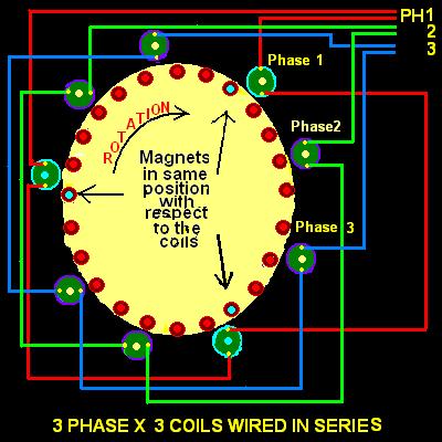
Time has proven that I am blind to the Obvious, some of the above may be True? |
||||
| oztules Guru Joined: 26/07/2007 Location: AustraliaPosts: 1686 |
The only information we need at the outset is the prop size and coil number per phase. We have .6m prop, so we can say that at 10mph we will have 5 watts available at the shaft @ 1000rpm. From this we see that if you have iron in the design, it probably won't work until maybe 12mph due to iron losses. As I don't know your design, I will have to assume axial flux.... any other type would be very poor in lower winds. So we just wind a 100 turn coil and place it in the stator position. We spin it at 1000 rpm .... we read the AC volts. Thats all we need to make the optimum coil for this machine. If we found say 1v ac, then we know we need to wind 200 turns per coil.... and use the thickest wire to get 200 turns into the space provided... thats it. Best coils you can do for that machine. Lets look at that again. We know we need cutin at 1000 rpm, pointless being less as only 2 shaft watts available at 8mph, and near 3 @ 9mph.... slim pickings indeed. So 10 mph it is. We wound a quick test coil of 100 turns and found we got 1vac@ 1000rpm. Now we know we have 3 coils per phase, so we multiply by 3..... now 3vac. per phase. We will wire it in star so we multiply that by 1.7 so 1.7x3vac=5.1vac Now we get to DC peak, by multiplying by 1.4 so 5.1x1.4 = 7.14vDC per star phase. So we know that 100 turns gets us to 1/2 cutin if we wound the whole stator for 100t/coil. We need 14v so we need twice the turns so 14.3v@1000rpm with 200 turns per coil. Done and simple and accurate. Now we could add a bit more for diode loss. For shotkky we may get away with .8v.... etc etc. Cut in voltage will be 13.7 or less, so even without that taken into account we will still start charging around the 1000rpm, which will be about 8-10 mph. (remember, with no load, the blades will try for 2000 rpm or twice the loaded TSR... so it will try to make something at less than 10mph. Now the design. For this type of performance you will do best with axfx .... even single magnet rotor and plain backing rotor. Any steel cut by the moving flux in the design will rob you of most of your lower power range. Stronger the magnets, the worse it will be. The magnet coil ratio and spacing is a waste of magnet. 2/3 of them are idle most of the time. wasted space. There is no cogging with axfx so 24:18 is best for this 24mag single plate design. On the above figures as examples, this would be 6 coils per phase of 100turns/coil. It would perform markedly better than 24:9. @20 mph you have available 38watts at the shaft so 2 + amps possible. If your design has iron in the stator, then your in trouble, as iron loss will be severe, and push startup well back, and output will be more likely to not impress. Armature reactance will become part of the problem as well with iron designs. In reality, a dual rotor of 12 mags per rotor and 9 coils will be best. No cogging and no iron drag, and the prop may stand a chance of starting up easily. At startup, your efficiency is at the max, so you will probably get your 1/3A. You will need to get to 27-28mph to get your 4A (shaft power there will be around the 90-100w, and efficiency will be falling as the wire will be pretty thin.) Thats for a TSR 7 blade in the calc above. ........oztules Village idiot...or... just another hack out of his depth |
||||
| Greenbelt Guru Joined: 11/01/2009 Location: United StatesPosts: 566 |
OZTULES; Thanks for Giving a rundown on the test coil, I find it interesting that your method is , well different, It has served you well and others.The statement below is a quote from your post. The magnet coil ratio and spacing is a waste of magnet. 2/3 of them are idle most of the time. wasted space. I would expect that wasted magnet would induce its contribution 9 times in its orbit. 2/3 of 24 = 16, 16 x 9 =144 packets of energy per turn over a 10th. of a million at 1000 rpm. 
To double the coils would double the counter EMF and I believe it would stall at cut in. Time has proven that I am blind to the Obvious, some of the above may be True? |
||||
| GWatPE Senior Member Joined: 01/09/2006 Location: AustraliaPosts: 2127 |
This assumes the coils are exactly the same, and the loading is exactly the same. Assume the loading was the same. With twice the number of coils, and the same total number of turns, then there would not be a stall problem, however the resistance could be halved, as in the same coil volume, twice the cross section wire could be placed. This would produce an alternator with higher electrical efficiency for the same magnet volume, at the same rpm. Gordon. become more energy aware |
||||
Sonny Regular Member Joined: 17/01/2010 Location: United StatesPosts: 66 |
You guys have me totally cornfused now, but I have to say a lot of the old ham radio stuff is coming back in focuse. I had totally forgotten Ohm's law when it comes to power formulas. I want to thank you all for getting me interested again in something I hadn't thought about in years. I very much enjoyed ham radio and all that went with it but family, kids and other things came first. Now that my kids are grown and I am retired, this is getting my mind working again in a way it hadn't for many years. 
Edited to add: what the heck am I talking about?? See my post, "I have a stupid question" on the wind mills forum. a complete novice |
||||
| Greenbelt Guru Joined: 11/01/2009 Location: United StatesPosts: 566 |
GWatPE This is what got it started, The project is not mine. The man wanted some help on flux and wire turns relationship. Some time in August he made a request fluux and turns of wire Drawing by MacG But I saw none offered other than suggestions to change his plan , do it different make it like my F&P or axial flux, Never use iron in a coil Melt your magnets down in a pot of aluminum . Perhaps the man would prefer to do it his way. I tried in my limited ability to give a basic accepted way to wind coils with known values of flux for Iron core coils. This is what he ask for. I understand the suggested extra copper and modified Loading, I presume air core coils or non magnetic core material would enhance efficiency though I have no way to verify it, I would be confident that you have ben there, done that. I also believe additional Iron C-coils will not give any improvement. For those who have notated the doubtful validity of some of my source info here is a page from an old Book that is one of the best I've ever opened, Published 1932 AUDELS MATHEMATICS and CALCULATIONS for MECHANICS. 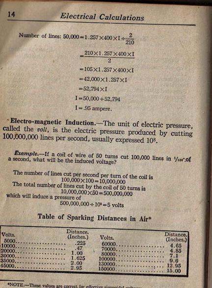
Time has proven that I am blind to the Obvious, some of the above may be True? |
||||
