
|
|
Forum Index : Electronics : Measuring voltage with a Picaxe
| Page 1 of 2 |
|||||
| Author | Message | ||||
| Gizmo Admin Group Joined: 05/06/2004 Location: AustraliaPosts: 5185 |
You know I really hate it when you press the wrong key and suddenly loose the entire post!  Any, try again. Any, try again.
OK. I am usig a Picaxe chip to monitor a 24v battery bank. Using the circuit below. Frig, I dont believe I have to type all this again. 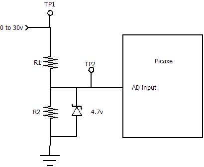
R1 is 47k, R2 is 8.2k. The zener is to protect the chip. The whole things works like the Piclog data logger. The AD input value is fed to the PC, that in turn uses a multiplier value to display the correct reading on the PC screen. To calibrate it, I fed 20 volts in, measured at TP1, and adjusted the multiplier to display 20v on the PC. I then adjusted the voltage down to 18v, measured at TP1, but the PC displayed 18.7v! 22 volts at TP1 displays as 21.4v. So its not very linear, useless as a voltmeter. Another test, this time with my multimeter on TP2. Adjusted the input voltage to read 2.5v at TP2, and adjusted the multiplier to display 2.5v on the pc. Adjusted the input voltage to read 2 volts at TP2 and it read spot on 2v on the PC. In fact, it was dead accurate from 0 to 4.7 volts. So it appears as though the input impedance on the Picaxe changes with voltage. As the impedance changes, it upsets the voltage divider and gives a non-linear response. Has anyone else come across this, and knows of a way to get around the problem without adding a op-amp. This also means the Piclog may not be very accurate at any voltage other than the voltage is was calibrated at. 
Glenn The best time to plant a tree was twenty years ago, the second best time is right now. JAQ |
||||
| GWatPE Senior Member Joined: 01/09/2006 Location: AustraliaPosts: 2127 |
Hi Gizmo, the problem is the input impedance of the picaxe. The 47k in your divider is quite high for a 24V system. I use a 27k and 2k for my std divider, up to 60V, and I believe "vasi" published some figs for the pic chip imput impedance. for battery sensing, the input range is quite narrow, and this is why I use an opto coupler, and a resistor/zener combo. The zener/opto gives the operating range of the battery to be the full 0-5V ADC input range. Just means that the calibration uses an offset and gain setting, and is a bit more fiddly to set the calibration. I don't think the picaxe is intended to be used without external linearization for accurate voltage sensing. A 2point calibration will help for the narrow operating range, but not if you need to go all the way to 0V. Gordon. become more energy aware |
||||
Downwind Guru Joined: 09/09/2009 Location: AustraliaPosts: 2333 |
Hi Glenn, I too have noticed the non linear response of the adc of a picaxe and have not found a way around it, other than to build compensation in within the program but even this has its problems. I have considered to use 2 adc and a transistor on one to give a reverse effect and read both pins and average the reading of the 2 but that aint that easy to setup either. Gordon sounds to be on the right track. Very interested in what you come up with. Pete. Sometimes it just works |
||||
| Gizmo Admin Group Joined: 05/06/2004 Location: AustraliaPosts: 5185 |
Yeah I think Gordons onto the right idea. Even though the voltage divider gives a range of 0 to 30v, I only need to read between 24 and 28 with some accuracy. A 2 point calibation should work fine, will let you know how it goes. Thanks Glenn The best time to plant a tree was twenty years ago, the second best time is right now. JAQ |
||||
| GWatPE Senior Member Joined: 01/09/2006 Location: AustraliaPosts: 2127 |
Hi Gizmo, I have just checked my version of the piclog, that PhillM has a couple of as well. The resistors on my cct are 56k, and 4k7, with a 4V7 zener protection. I only use the SMD version of the picaxe08M as you know. Here is the output ADC counts v input voltage, and plotted on EXCEL. 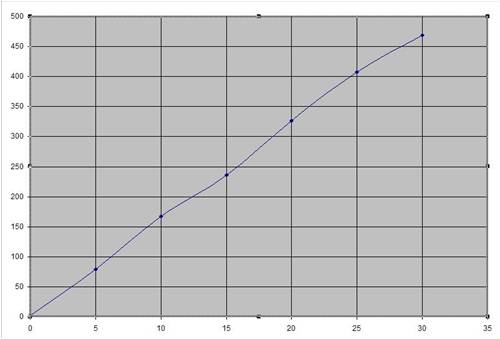
The unit is linear within the limits of the chip. I could extend the range, all the way up to 60V. I use 27k, and 2k0 resistors now, and the linearity is slightly improved. I can't see why you are having problems, but maybe the socket??? Gordon. become more energy aware |
||||
| davef Guru Joined: 14/05/2006 Location: New ZealandPosts: 499 |
For the ATmega32 � 10-bit Resolution � 0.5 LSB Integral Non-linearity � �2 LSB Absolute Accuracy Even at 8 bits I would expect say 1 bit which is ((1/255) * 30V) = 0.1V Is there a linearity and input impedance spec for your part. I would carefully remove the zener and see if that makes a difference. Then, could you tolerate more current through your divider network? Try a 4K7 and a 820 Ohm just to see if it really is current drawn by the ADC that is causing the non-linearity. |
||||
| GWatPE Senior Member Joined: 01/09/2006 Location: AustraliaPosts: 2127 |
Here is the graph, of the same cct, extended to a measured 65V input. As I said before, I see no problem. 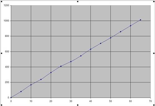
Gordon. PS Edit: There may be a problem with the supply to the chip, as the ADC reference is the 5V supply. become more energy aware |
||||
Bryan1 Guru Joined: 22/02/2006 Location: AustraliaPosts: 2136 |
G'day Glenn, Below is a circuit I use for measuring 24 volts to an input ADC on a pic. I use 2off 10V zeners in series then a 10K pot for the fine adjustment, the 1K resistor protects the input pin and the other zener is there to clamp the input to 5 volts incase of a over voltage situation. 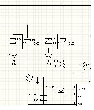
Cheers Bryan |
||||
| GWatPE Senior Member Joined: 01/09/2006 Location: AustraliaPosts: 2127 |
Hi Bryan, the cct you posted, gives an expanded scale voltage window, but zeners are reasonably noisy components. If the cct works, then this shows that the Pic input has quite a low impedance, as the only ground path for the input is within the chip. It is usually better to scale the voltage externally, and not rely on the internals of the ADC in the chip. Gordon. become more energy aware |
||||
| Gizmo Admin Group Joined: 05/06/2004 Location: AustraliaPosts: 5185 |
This is a interesting thread. I like Bryans idea of series zenners to give an expanded scale. I'll fire the circuit up again tomorrow and take some more measurements, maybe I was doing something wrong. Originally I had a 470k and 82k resistors for the divider, I asumed the Picaxe had a high input impedance like a multimeter, but Vasi said something about the 10k imput impedance so I changed to 47k and 8.2k. Maybe just using a lower value resistor will work as Gordon points out. I'll try a 12k and 2.2k to see how it performs, but I think I'll end up going for the zenners. Glenn The best time to plant a tree was twenty years ago, the second best time is right now. JAQ |
||||
| GWatPE Senior Member Joined: 01/09/2006 Location: AustraliaPosts: 2127 |
Hi Gizmo, If you do opt for a narrow range window sensing, then opt for a 2:1 divider to ground, of 1k resistors, and at least 1uF bypass across the ADC input to ground. This will give 0-5V on the ADC input for 20-30V battery, with a 20V zener voltage. The zeners give a factor of 3 increase in sensitivity, but will require a 2 point calibration. My LiPo battery cell monitoring uses the LED in the opto, as well as the isolation to give an expanded scale, and electrical isolation. I used the zener and opto coupler to measure the voltage of my 200V solar panel, with a micro 0-5V ADC. I have the 56k, and 4k7 resistors and a 1uF bypass on my piclog board, and the calibration comes out as above. There is not much wrong with the picaxe ADC, as long as the external resistor to ground is 4k7 or lower, to get the correct input scaling. Gordon. become more energy aware |
||||
fillm Guru Joined: 10/02/2007 Location: AustraliaPosts: 730 |
Hi Glenn , The voltage measurement on the boards of Gordons work very well and stay linear though out the range of volts with my 48v system . I remember when I had your origional Piclog the volts staying linear up in the 52v~62v was a bit of a problem and would then cause the watts to not read correctly PhillM ...Oz Wind Engineering..Wind Turbine Kits 500W - 5000W ~ F&P Dual Kits ~ GOE222Blades- Voltage Control Parts ------- Tower kits |
||||
| Gizmo Admin Group Joined: 05/06/2004 Location: AustraliaPosts: 5185 |
OK, I've done some more testing, and the weirdness continues. I'm using two of the ADC inputs side by side for comparison. ADC 1 has the original 47k and 8.2k voltage divider, and ADC 2 has a 12k and 2.2k voltage divider. The hope was the lower imput impedance would give a linear response. It didn't. Its better, but not much. I calibrated both ADC's at 15v, then adjusted the power supply to 12v and 18v. Below are the readings I got from the ADC's ADC 12v 15v 18v ADC1 12.62v 15v 16.58v ADC2 12.27v 15v 17.13 This is weird, and the only thing I can put it down to is a ADC impedance that changes with input voltage.
Next I'm going to try adding a 1uF cap across the ADC input. I've checked the zener and 5v supply, all good. Glenn The best time to plant a tree was twenty years ago, the second best time is right now. JAQ |
||||
| Gizmo Admin Group Joined: 05/06/2004 Location: AustraliaPosts: 5185 |
OK, caps didn't make any difference. Time to google the Picaxe forums. The best time to plant a tree was twenty years ago, the second best time is right now. JAQ |
||||
| Janne Senior Member Joined: 20/06/2008 Location: FinlandPosts: 121 |
Hi Glenn, What picaxe are you using? If it's one of the X2-range axes, have you issued the ADCSETUP command before reading the ADC values? Also it would be interesting to see if the order matters, i mean if the values stay the same if adc2 is measured first and adc1 after that. If at first you don't succeed, try again. My projects |
||||
| Gizmo Admin Group Joined: 05/06/2004 Location: AustraliaPosts: 5185 |
Hi Janne Its a 20X2 chip. I've issued the adcsetup command let adcsetup = %0000111111111111 since I'm using all 11 ADC inputs. Been doing some maths with my trusty old calculator I stole from a previous employer, along with all my pens. At 1.5 volts input to the ADC, it has a current draw of 0.01mA, so a resistance of 150k. At 2.5 volts, its current is 0.11mA, and a resistance of 22k. I should test at 1, 2, 3 and 4 volts, but my current setup wont let me without firing up the soldering iron. Glenn The best time to plant a tree was twenty years ago, the second best time is right now. JAQ |
||||
| Downwind Guru Joined: 09/09/2009 Location: AustraliaPosts: 2333 |
I dont think you will get away from the problem as by memory it has more to do with how the picaxe steps internally from 1 adc step to the next. I dont think you will find they are entirely linear. If you do the same test with a pot set as a voltage divider across 5 volts it wont step exactly linear either. This is why i am interested in what you find out as it has been a bug bare of mine too. Pete. Sometimes it just works |
||||
| Downwind Guru Joined: 09/09/2009 Location: AustraliaPosts: 2333 |
Looking at the picaxe data the adc steps in 16 steps and from the chart i dont see how it can be exactly linear. 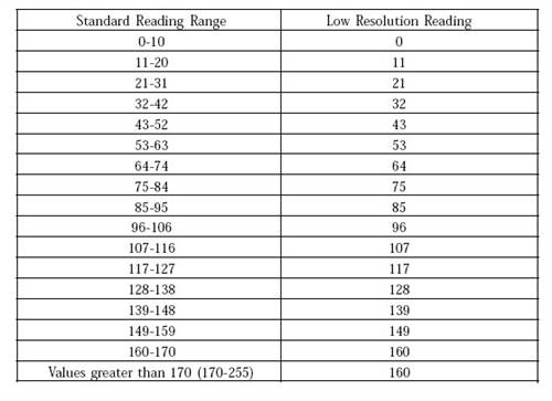
Correct me if im wrong. Pete. Sometimes it just works |
||||
| Gizmo Admin Group Joined: 05/06/2004 Location: AustraliaPosts: 5185 |
That would be a the low resolution READADC command, with 8 bit resolution. I'm using the 10 bit readadc10 command, gives 1024 levels. What I did find is the ADC is linear for a constant voltage source. If I feed in 2 volts, I'll get double the reading for 1 volts. Its when we add a voltage divider that the problem pops up. It would appear as though the 08M chip doesn't have this problem. I need to do some tests, but it may have to wait, I need to get this thing going so I'll calibrate it for 24 volts and see if I can get it more accurate with software. Anyone remember their algebra? Glenn The best time to plant a tree was twenty years ago, the second best time is right now. JAQ |
||||
| vasi Guru Joined: 23/03/2007 Location: RomaniaPosts: 1697 |
-= erased the text - did not read first page :P =- Not all 18F chips are so good at ADC. By example, 18F252/18F452 is accurate and stable, much better than a 18F2550/18F4550. Vasi Hobbit name: Togo Toadfoot of Frogmorton Elvish name: Mablung Miriel Beyound Arduino Lang |
||||
| Page 1 of 2 |
|||||
| The Back Shed's forum code is written, and hosted, in Australia. | © JAQ Software 2026 |
