
|
|
Forum Index : Electronics : Measuring voltage with a Picaxe
| Author | Message | ||||
| GWatPE Senior Member Joined: 01/09/2006 Location: AustraliaPosts: 2127 |
Hi Gizmo, I have a unit I can test with. I will add the same resistors to an input of a 20X2, and a 14M, and possibly a 28X2, and compare to the 08M, across the same 0-65 V range. Will get back tomorrow if possible. Gordon. become more energy aware |
||||
| vasi Guru Joined: 23/03/2007 Location: RomaniaPosts: 1697 |
Found this from Microchip about ADC accuracy http://ww1.microchip.com/downloads/en/AppNotes/00693a.pdf Hobbit name: Togo Toadfoot of Frogmorton Elvish name: Mablung Miriel Beyound Arduino Lang |
||||
| vasi Guru Joined: 23/03/2007 Location: RomaniaPosts: 1697 |
I found here some observations regarding to Multiple ADC inputs and the conclusion was that [quote] The ADC circuits will affect each others' readings. [/quote] and the author come with some advices. The source is here. Hobbit name: Togo Toadfoot of Frogmorton Elvish name: Mablung Miriel Beyound Arduino Lang |
||||
Downwind Guru Joined: 09/09/2009 Location: AustraliaPosts: 2333 |
I had read the microchip adc data before as it is in every data sheet for every pic that picaxe uses. And as i said earlier the steps internally are not exactly linear. I think page 8 sums it up in this use with the reference voltage used being the line voltage. I logged on to say decoupling capacitors would be the biggest benifit in this case. Then read Vasi's second post which also confirms this. Once every ttl circuit was covered in decoupling caps on everything, but we often forget to include them nowdays with less noise in current chips and circuits. I still dont see a way around the reading variations as i think it is somewhat a internal problem within the micro. Noise wont help it but doubt if you will ever solve it completely. The referance to adc reading while in sleep mode might be worth a try. I have noticed that the adc readings are noisier on some chips than others from different batches i have had. So maybe you have a Monday or a Friday chip Glenn 
There also might be something in the fact that Gordon uses Smd as these are also noted to be not so subject to circuit noise, as well he uses double sided boards that also helps in noise reduction and vero board is bad for that with wire jumpers etc. Pete. Sometimes it just works |
||||
| vasi Guru Joined: 23/03/2007 Location: RomaniaPosts: 1697 |
Also, others are using this method: - make 16 readings (with appropriate delay between them); - sort them; - remove first 4 results and last 4 results; - do averaging remaining values. Hobbit name: Togo Toadfoot of Frogmorton Elvish name: Mablung Miriel Beyound Arduino Lang |
||||
| Downwind Guru Joined: 09/09/2009 Location: AustraliaPosts: 2333 |
I found this on the pixaxe forum that might be of interest to the problem you are having Glenn. LINK HERE I dont know if it will let you view the entire thread without being a member but give it a go. Basically it says the problem is with using the zener diode and to give it the flick as with a correctly calculated resistor divider it should not hurt the adc input if the voltage goes above 5 volts as the current will be limited if the divider is setup correctly. Even thebackshed gets a mention. So maybe it will all work correctly and my views on the adc inputs have been wrong 
( I dont mind being wrong when i understand why) Pete. Ps...If it wont let you view the thread let me know and i will copy the relevent comments. Sometimes it just works |
||||
| GWatPE Senior Member Joined: 01/09/2006 Location: AustraliaPosts: 2127 |
I have just finished testing of each of the other picaxe chips I have on hand, including the 14M, 20X2, and 28X2. I set up test boards with each chip, and used the same resistor divider. This was 27k, and 2k0. Here is a plot of the cmparison, and the raw data. 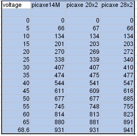
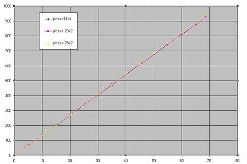
The graphs are almost superimposed. This concludes that the is not a problem with the Picaxe ADC, and the problems must originate with the circuitry outside the chip. It is possible that the leakage current through the zener may be the cause, as this is the only additional component to my test. I usually use a diode back to the 5V rail, as this is similar to the internals of most chip inputs. The zener removal will be an easy step. Most inputs can withstand overvoltage with limited current. On a micro, with inputs that can change to outputs, a zener can damage the output function, if the output is allowed to be made high. something to consider in future. Gordon. become more energy aware |
||||
| Gizmo Admin Group Joined: 05/06/2004 Location: AustraliaPosts: 5015 |
Thanks guys, great work. As soon as I get home I'll remove a zener and see what happens. Maybe I have a batch of leaky zeners? The diode back to the +5v rail is a good idea Gordon. Glenn The best time to plant a tree was twenty years ago, the second best time is right now. JAQ |
||||
| Gizmo Admin Group Joined: 05/06/2004 Location: AustraliaPosts: 5015 |
Just read the forum thread you posted Pete, seams to confirm the zener is the bugger causing my problems. I should have listened to Dave on page 1 of this thread and tried removing the zener first. I'll have to add a few notes and changes to the Piclog page. Glenn The best time to plant a tree was twenty years ago, the second best time is right now. JAQ |
||||
| Gizmo Admin Group Joined: 05/06/2004 Location: AustraliaPosts: 5015 |
Bingo!!!! 
It was the zeners's. I snipped out two zeners, one on the 47k/8.2k combo and another on the 12k/2.2k combo. Adjusted the supply from 10 to 20 volts, and both ADC's tracked perfectly, to within 0.02 volts. So there you go. Big thanks to everyone. 
I'll update the Piclog page this weekend. Glenn The best time to plant a tree was twenty years ago, the second best time is right now. JAQ |
||||
| davef Guru Joined: 14/05/2006 Location: New ZealandPosts: 499 |
I wouldn't be happy relying on the input circuitry of the ADCs to handle over-voltage. The JEDmicro AVR200 dev board uses a TL7726 (Texas Instruments hex clamping devices) to protect the ADC inputs. Or better 4V7 zeners! |
||||
| Gizmo Admin Group Joined: 05/06/2004 Location: AustraliaPosts: 5015 |
I'll use a diode to the +5v feed to clamp any inputs down to 5.6v, and a resistor in series with the ADC input. Hopefully thats enough to protect the chip. Yeah I figured a 4.7v zener would do the job fine, but I didn't even think of its leakage current. I tend to have "software" vision when it comes to electronics. A 4.7v zener should be like... if V > 4.7 then clip V - 4.7 But of course, electronics isn't that simple. Glenn The best time to plant a tree was twenty years ago, the second best time is right now. JAQ |
||||
| Downwind Guru Joined: 09/09/2009 Location: AustraliaPosts: 2333 |
Dont you just luv the challenges electronics give
With the resistors you are using you would have around 2mA at the adc input and the input can handle up to around 20mA so a little over voltage should not be an issue. The diode to the 5v rail should take care of any excess even though is is most likly not needed as it is provided internally. 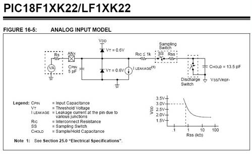
A circuit fix that requires the removal of a component is always better than needing to add them. Pete Sometimes it just works |
||||
| vasi Guru Joined: 23/03/2007 Location: RomaniaPosts: 1697 |
And this is for me (that second part - from the link Downwind posted): [quote=BeanieBots]Indeed, there are TWO parts to designing a potential divider. The obvious part, the ratio that gives the divider action. Vout=Vin*R1/(R1+R2) and the part most people ignore, forget or don't even realise. The impedance seen by the ADC input. (must be <10k for most PIC inputs). Z=R1*R2/(R1+R2). As wolfgang explains, it's Thevenin's Theorem. Often stated as the "Thevenin equivalent source". The output of a POT can be considered as a new voltage source with a single series resistor. Voltage and resistance values are given by the equations above. [/quote] Hobbit name: Togo Toadfoot of Frogmorton Elvish name: Mablung Miriel Beyound Arduino Lang |
||||
