
|
|
Forum Index : Electronics : Piclog over the net.
| Author | Message | ||||
| Janne Senior Member Joined: 20/06/2008 Location: FinlandPosts: 121 |
Hi Glenn, No I'm still using the shunt on the negative line, but I needed isolation on the serial connection, because of non-isolating power adapter of my laptop (battery - is now connected to the serial port ground via the power adapter). But like you say, with this isolated configuration the shunt on the positive line would work as well, then you would just need to use a 7905 regulator, and invert the current measurement, 1023 on the ADC pin would mean zero current. If at first you don't succeed, try again. My projects |
||||
| Janne Senior Member Joined: 20/06/2008 Location: FinlandPosts: 121 |
Nothing easy on this project it seems.  One thing I didn't test was the new logger configuration with piclog.. It just so happens that piclog does not enable the DTR pin while opening the serial port. To make the frustration complete, it seems that the "just basic" - language is not even capable of doing that - so much for the idea of just making a quick source code update. One thing I didn't test was the new logger configuration with piclog.. It just so happens that piclog does not enable the DTR pin while opening the serial port. To make the frustration complete, it seems that the "just basic" - language is not even capable of doing that - so much for the idea of just making a quick source code update.
However, on justbasic forums there are discussions of using pin 7 for power, that might be an alternative. Or just bin the whole logger and go have a beer 
edit: It seems like the DTR pin can be manipulated by using "liberty basic", an upgraded version of the free justbasic.. I just downloaded it and the modified program at least seems to compile ok, but I'll have to wait until tomorrow to see if it works ok. If at first you don't succeed, try again. My projects |
||||
Downwind Guru Joined: 09/09/2009 Location: AustraliaPosts: 2333 |
Murphys law >>>> A quick fix will always take longer <<<<<< Pete. Sometimes it just works |
||||
| Gizmo Admin Group Joined: 05/06/2004 Location: AustraliaPosts: 5016 |
Keep us posted on Pin7 and/or Pin4 with Liberty Basic. Have you looked at using a small inverted from a old network card? http://www.thebackshed.com/Windmill/articles/PanelMeter.asp I've used them before when I needed a isolated power supply. Glenn The best time to plant a tree was twenty years ago, the second best time is right now. JAQ |
||||
| Janne Senior Member Joined: 20/06/2008 Location: FinlandPosts: 121 |
Well now it's logging away happily. I didn't get the DTR pin (pin 4 ) to work even with liberty basic, it is propably possible but I couldn't figure out how. Instead, pin7 can be used to provide pullup, and by the default settings the piclog uses it is already powered.. So I just connected the pullup to pin7, and now it works. Only problem seems to be the anemometer interface, it seems to be picking up contact noise.. I'll still need to tweak that one a little. If at first you don't succeed, try again. My projects |
||||
niall1 Senior Member Joined: 20/11/2008 Location: IrelandPosts: 331 |
hi Janne can i ask how your anemometer setup works ? ..they would seem to make a good fun project build on their own with the piclogger cct i drive by a couple of small weather stations on the motorway layby most weekends and am always a bit temped to stop and nick the anemometer just to see whats inside it niall |
||||
| Gizmo Admin Group Joined: 05/06/2004 Location: AustraliaPosts: 5016 |
Good to hear its working Janne. I built my anomometer using a 3 wire hall sensor from a PC fan and a magnet hub from a PC hard drive. The hub has 8 magnets, so I get 4 reasonably clean pulses per revolution. Do you have a cro? They can be handy to help you choose a suitable filtering capacitor. It is possible to de-bounce a noisy switch using software within the PicAxe chip. Instead of usng the count command, you can use a combination of pulsin and pause commands. The pulsin command waits for a change of state of the switch, and a pause command is then used to skip over any noise, followed by another pulsin, pause and pulsin command to measure the duration of one switcing cycle. Then add some picaxe integer maths to work out how many pulses per second. I havn't tried this, but it should work. Glenn The best time to plant a tree was twenty years ago, the second best time is right now. JAQ |
||||
| Janne Senior Member Joined: 20/06/2008 Location: FinlandPosts: 121 |
Hi, The anemometer I use is this; http://inspeed.com/anemometers/Vortex_Wind_Sensor.asp So it just has a reed switch sender. I think the main problem is the bc847, which is pulling down a +5V on an input pin without much filtering at all.. Though I'm not 100% sure, the problem might also be for exaple in the reed relay, as my anemometer display also just started to act weirdly, which has been working perfectly before this. I do have a cro, but there's no grid power on site to run any tests to see what kind of noise I have. I do have a square wave ups in there, but I'm afraid to run the cro on that, I'd hate to let the magic smoke out of it. So at least for now, I'm trying to go forward with the gut feeling. 1st of all, I'm going to reduce the gain of the transistor, and also add some filtering to the base & picaxe input. On top of that, I'm thinking of putting a nice sized RC snubber to the end of the anemometer sensor cable to hopefully tame the voltage spikes to some amount. If at first you don't succeed, try again. My projects |
||||
| niall1 Senior Member Joined: 20/11/2008 Location: IrelandPosts: 331 |
that anemometer looks very rugged Janne...i hope you get it to work the way you want your projects page is an inspiration looking through it ...i particularly like this pic.... 
mind boggling ....  niall |
||||
| Janne Senior Member Joined: 20/06/2008 Location: FinlandPosts: 121 |
Glad you enjoy the pics in my projects album. The big machine was quite impressive with the 12m blade set, but ultimately it was a failure as it was treaded with various kind of problems, most of them relating to the pitch mechanism. I do have a 2hr+ video where my late father discusses about the machine with lots of info about bigger mills in general also, but I'm having a hard time figuring out how to host the 2.5GB video file. If anyone has got any bright ideas about that, mayby drop me a PM? Back to the subject... I was able to fix the anemometer. I reduced the gain of the transistor, and added a 4.7�F tantalum cap to the picaxe input pin.. And also replaced the pullup resistor with a 4.7k one. Now the anemometer part seems to work nice also. This all also added a new problem. As the anemometer now loads the ground lead more too, it's starting to disrupt the measurements. So I went ahead and ordered a bunch of high side shunt monitor chips.. I guess I'm going to build a new board with all the modifications "hard wired" when they arrive. And also the logger has evidenced that the production numbers are pretty dismal, even worse than what I figured out of hand.. But I guess that's the hard reality of wind, having the machine in a relative short tower, + living inland of Finland  If at first you don't succeed, try again. My projects |
||||
| Gizmo Admin Group Joined: 05/06/2004 Location: AustraliaPosts: 5016 |
With a bit of free time over the Christmas break, I've been working on a few changes to the PicLog. A few software updates, and going wireless. Bought a couple of 433MHz wireless modules from Jaycar Electronics to try out, a transmitter and a reciever module, Link. Fitted the transmitter to the PicLog circuit board. 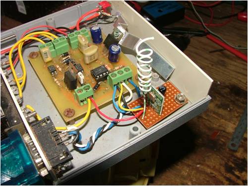
I curled up the aerial to reduce its gain, the reciever is only a couple of meters away. I used one of Petes logging circuit boards as the receiver. 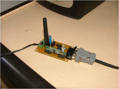
With a few software changes to the PicAxe code for both modules, and a lot of help from Pete, I soon had the PicLog working wireless. Next I'll refine the code and document it onto the web site, along with details on wiring up the modules. It will be interesting to see what sort of range I can get with a standard dipole aerial, and maybe experiment with a yagi or old satelite dish. I'm working on a update to the PC software. A few more features, like daily peaks, and a running watts graph to add a bit of bling. This screen shot is the new software running on my Win2k server. 
Glenn The best time to plant a tree was twenty years ago, the second best time is right now. JAQ |
||||
| vasi Guru Joined: 23/03/2007 Location: RomaniaPosts: 1697 |
Hi Glenn, Very nice project! About software, it is possible to add custom user-defined inputs? Vasi P.S. For ATMEL fans, I did my first SD card logger with Arduino language and ATmega644p, on an EvB4.3 version 4 board. Just to see if I can manage it. The goal is to move this to a Microchip microcontroller, using a free compiler (well, there are compilers with anything you want in their library as mikroBasic, mikroPascal, mikroC and affordable - they have also SD card and USB library). The page is in construction, I will add some real photos and a movie. Hobbit name: Togo Toadfoot of Frogmorton Elvish name: Mablung Miriel Beyound Arduino Lang |
||||
| Gizmo Admin Group Joined: 05/06/2004 Location: AustraliaPosts: 5016 |
Hi Vasi The PC software is written in JustBASIC, the source is included in the download, so you can add as many functions as you like. The PicLog uses a 08M chip, with only 4 inputs. There is no reason why you couldn't use a 20M chip or similar to get more inputs, just change the software to suit. Glenn The best time to plant a tree was twenty years ago, the second best time is right now. JAQ |
||||
powerednut Senior Member Joined: 09/12/2009 Location: AustraliaPosts: 221 |
nice work vasi |
||||
| Downwind Guru Joined: 09/09/2009 Location: AustraliaPosts: 2333 |
Good to see it all worked out for you Glenn, I bet you found the wireless modules only to easy once you looked at a few code examples, and wished you had dabbled with them long ago. Im sure it has opened thoughts of many projects for other uses for these wireless modules. Perhaps you should do a "How to use the 434mhz modules" while it is fresh in your mind, as im sure others will also then follow with dabbling in their use. I found a distinct lack of information available when i first used them, and took weeks of experimentation to find a reliable method of use.(all to simple when you know) There is still many discussions on other forums over the reliable use of these modules, so a "how to" would help many. Just one request, can you use "SYMBOLS" in any code examples.......(please, please, beg, grovel, crawl, wish, plead, request, hope, plead, plead.............) {private joke, as i hate spaghetti code. (b1 = w3 loop to b7 and then to b12 etc, etc)} Nice to see the project up and running. 
Pete. Sometimes it just works |
||||
| vasi Guru Joined: 23/03/2007 Location: RomaniaPosts: 1697 |
Yes, i would like that too, please! Vasi Hobbit name: Togo Toadfoot of Frogmorton Elvish name: Mablung Miriel Beyound Arduino Lang |
||||
