
|
|
Forum Index : Electronics : Yet another charge controller circuit
| Author | Message | ||||
| SpmP Newbie Joined: 10/10/2010 Location: New ZealandPosts: 32 |
Good day all. back on the wind turb. warpath, and have been trying to derust my electronics knowledge and put together a simple control circuit for a F&P wind turbine, unmodified, open circuit from between 30-400V DC after the bridge. Can any one look at this and tell me if its alright. I borrowed a few bits from the picaxe circuits. My main concern is: Will I need more opto isolation for the micro (an AVR butterfly at this stage). The load is resistive at the moment (light bulbs/heaters etc), but later on the pwm will be on the o/p of an smps (laptop psu, amazing things work from 30-300v! ->15v what more can you ask for!) I have just sussed an opto isolated high side driver. High side? Low side? any preference. High side seems safer, and easier isolated. This is all done in LTSpice, so used LT components. 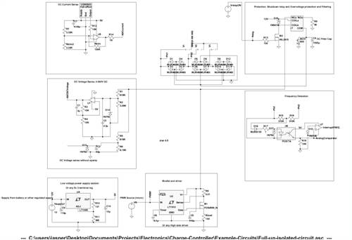
Sorry for the size, any smaller and I couldn't read things. Some bits of the 'genny' didnt come through. just voltage sources attached to the bridges. TIA! Jasper |
||||
| Gizmo Admin Group Joined: 05/06/2004 Location: AustraliaPosts: 5016 |
Hi Jasper If you upload the circuit as a GIF file instead of a JPG file, it will be be saved at twice the size and should be a lot easier to read. Glenn The best time to plant a tree was twenty years ago, the second best time is right now. JAQ |
||||
Downwind Guru Joined: 09/09/2009 Location: AustraliaPosts: 2333 |
My old bugger eyes can not make head nor tail of your schematics. As Gizmo said try posting them larger and even attach the file as a PDF so i can download it for a closer look. I would go high side for the current as it gets away from any ground loop problems. Although i don't see why you would be monitoring current for a charge controller. What is your reason for using a unmodified stator as it is a very inefficient way of doing things, and secondly it is extremely dangerous with the high voltage it can produce. You do realize the voltage produced is more than able to KILL YOU, or someone else 
Pete. Sometimes it just works |
||||
| SpmP Newbie Joined: 10/10/2010 Location: New ZealandPosts: 32 |
Thanks. I will try a gif, and attach a pdf. Downwind, I am monitoring current as this is part of a MPPT controller and we want some idea of maximum power through VA. I am using an unmodified stator as in the past I have had ~500m between turbine and batteris. With low voltages I was loosing far too much. So I figure keep it high and use an smps to swith it down, and overall the losses would be less. Is this wrong? Please explain. The voltages are high, around 300-400 max Ive seen so far. DC too so it is a little scary. I just treat it with the respect I give mains appliances. 
Cheers. Jasper (wow! gif is so much better here!) 2010-10-11_045851_Full-circuit.pdf |
||||
| Downwind Guru Joined: 09/09/2009 Location: AustraliaPosts: 2333 |
Im just wondering how the circuit will handle the wide range of voltage that you will get. It is not easy to design for anywhere between 0 to 400 volt monitoring and think you will run into problems with try to monitor such a wide voltage scale. I will download the file and digest it further but at a quick look you dont appear to list all the components and values intended for use. Pete. Sometimes it just works |
||||
| SpmP Newbie Joined: 10/10/2010 Location: New ZealandPosts: 32 |
Isolated dc voltage measurement without an expensive (and hard to supply with power) isolation amplifier, or voltage to frequency converter + opto, or expensive linear opto has got me beaten. Any ideas? (I thought maybee capacitive divider, but thats only one phase i.e not rectified dc voltage., and wide freq range...) Is the voltage divider network protected with a zener clamp going to be safe enough for a micro? Would the lm741 affor much proection? Is the problem ground loop tho? i.e having the HV DC ground and the low 12/5v ground connected. cheers. |
||||
