| Author |
Message |
GWatPE
Senior Member

Joined: 01/09/2006
Location: AustraliaPosts: 2127 |
| Posted: 12:33pm 23 Nov 2010 |
 Copy link to clipboard Copy link to clipboard |
 Print this post |
|
I have had the opportunity to see how multiple GTI interact with a battery RE system.
My setup has shown that transformer coupled GTI should not be connected together on the DC side.
I have a solar panel with an outback MPPT supplying a battery. A PowerJack GTI is controlled to turn ON when the battery has excess charge that needs to be diverted. I also have tested a 50Hz transformer coupled latronics GTI across the solar panel as well. The theory was that when the battery is full, the MPPT will shut down, and allow the solar panel voltage to rise to a point where the latronics GTI would reach cutin voltage and surplus power would go out to the grid. NOT SO!!.
The Latronics took power from the grid, in the reverse action, as a synchronous battery charger. This power was recycled through the Outback MPPT, to the battery, and then back to the grid through the PowerJack GTI.
I will need to add diode blocking to prevent the Latronics from reverse acting this way.
Here is the proof of this happening.
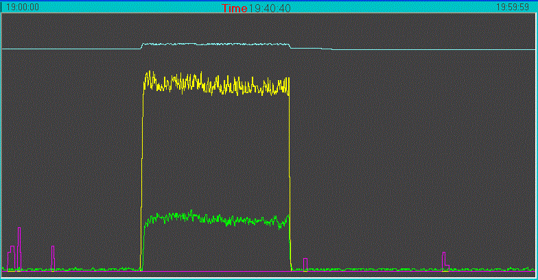
The tell was the 15minute duration. This is the length of time the Latronics stays connected after first woken up to try and sustain a grid connection in low wind conditions.
The use of current shunts to measure power will not easily pick up this behaviour. It happened twice, so was not just a glitch.
Gordon.
PS edit: the outback current was the yellow trace, tthe Powerjack current was the green trace. The Lt blue trace was the battery voltage. The battery was clearly being recharged during this time, due to the jump in voltage.
Edited by GWatPE 2010-11-24
become more energy aware |
| |
VK4AYQ
Guru

Joined: 02/12/2009
Location: AustraliaPosts: 2539 |
| Posted: 01:13pm 23 Nov 2010 |
Copy link to clipboard |
Print this post |
|
Hi Gordon
I cant get my head around how it is going backwards through the Islanding on the outback, I realize there is a sensing current but how it is able to get significant current back to the battery has me tossed.
All the best
Bob
Foolin Around |
| |
GWatPE
Senior Member
Joined: 01/09/2006
Location: AustraliaPosts: 2127 |
| Posted: 10:12pm 23 Nov 2010 |
Copy link to clipboard |
Print this post |
|
Hi Bob,
islanding is about AC connection, and AC impedance.
As far as the inverter is concerned the AC is OK.
The H-bridge that would normally drive the transformer is the bi-birectional component. There does not appear to be any direction sensing in the DC current measuring within the Latronics GTI during the 15min window. I have a knack for finding defects, so this would not be an exception. [I have to be careful, pointing out problems with hardware or software has caused me problems here on the forum].
These units could make a good synchronous battery charger if the 15min feature could be controlled.
The blocking diode will fix the problem for now.
Gordon.
PS edit: the outback is a half bridge design solar MPPT, so this component has a bi-directional aspect, anlike a normal buck converter. Current direction sensing controls the internal relay, that turns the unit OFF when current reverses. The Latronics GTI does not seem to operate the internal disconnect relay with reverse current. This may be a design fault with the microprocessor coding.Edited by GWatPE 2010-11-25
become more energy aware |
| |
VK4AYQ
Guru
Joined: 02/12/2009
Location: AustraliaPosts: 2539 |
| Posted: 12:05am 24 Nov 2010 |
Copy link to clipboard |
Print this post |
|
Hi Gordon
Very interesting, it may have been an oversight in the design, as we tend to push the limits with these things doing things not originally called up in the design.
What is the amps out as a charger, because the time limit could be used for a top up and a reset to start again.
All the best
Bob
Foolin Around |
| |
GWatPE
Senior Member
Joined: 01/09/2006
Location: AustraliaPosts: 2127 |
| Posted: 07:33am 25 Nov 2010 |
Copy link to clipboard |
Print this post |
|
Hi Bob,
I would have replied yesterday, but a forum message stating that I had posted more messages than I was allowed came up. Must be a recent forum Block Gizmo has introduced to discourage SPAM. I must have missed the advice notice when this was sent out.
Anyway, I am not sure about the use of a GTI as a battery charger really. Mine was putting 15A back into the battery during the 15min period. Since the addition of the blocking diode the unit is now operating correctly as a GTI.
I do believe that the bidirectional aspect is not fully appreciated. I remember in 1990, a solar car blew up the motor controller through the bi-directional nature of the motor braking system.
The low input voltage, mains transformerless designs have inbuilt blocking diode functionality, through the DC-DC up converter typically used in the design. The additional componentry used, does reduce the system power transfer efficiency compared to a torroidal mains transformer. The high voltage designs like SMA use have a more elaborate safety and relay isolation system. Too complex to go into here. For interest, you may wish to look at some block diagrams that SMA provide in their literature to see how they do it.
Gordon.
become more energy aware |
| |
