
|
|
Forum Index : Electronics : SMD chips
| Page 1 of 2 |
|||||
| Author | Message | ||||
Downwind Guru Joined: 09/09/2009 Location: AustraliaPosts: 2333 |
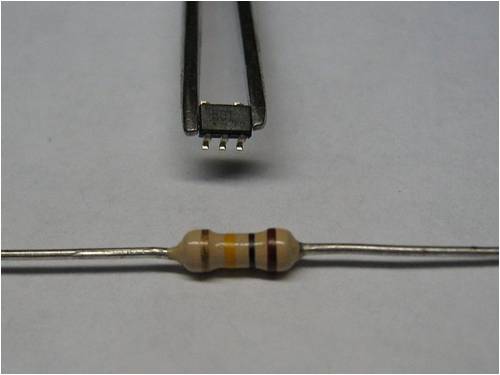
Smd chips make me marvel at how tiny they can be and the job they do. Until you drop one on the floor as i just done and spent the next hour looking for it. It was a shunt monitor chip, and this tiny little package can read a shunt with 100 amp flowing through the shunt and up to 80 volt. It amazes me till it comes to soldering them onto the board. The resistor in the photo is a standard 1/4 watt carbon resistor for size comparison. The chip is sitting in my tweezers. 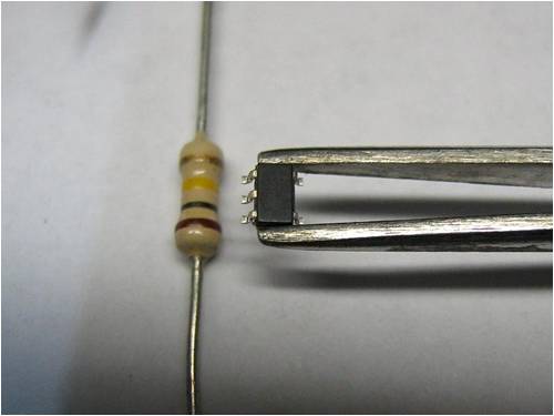
Now must get back to soldering it onto the board before i loose it again 
Pete. Sometimes it just works |
||||
| VK4AYQ Guru Joined: 02/12/2009 Location: AustraliaPosts: 2539 |
Hi Pete I can hardly see them, for our kind of work I think it is ridiculous miniturisation. I ordered some by mistake instead of dip but cant see how to solder them without a big magnifying glass and my hand shakes so is a lost cause. Good luck with using them. All the best Bob Foolin Around |
||||
| Tinker Guru Joined: 07/11/2007 Location: AustraliaPosts: 1904 |
Pete you could use your vacuum cleaner when looking for it  . Just remember to tie some fine gauze across the nuzzle before turning it on . Just remember to tie some fine gauze across the nuzzle before turning it on  . .
Soldering these SMD is just doable if their leg count is well below centipede range  . Unsoldering the faulty one is the real challenge. I had to remove two diodes (only two legs) and did not have a forked soldering tip or similar. A tiny nozzle heat gun got them off but one has to be very careful not to burn anything in the process. I would prefer the older (wire legged) type of components, IMO SMD are the thing for robots not aging technicians . Unsoldering the faulty one is the real challenge. I had to remove two diodes (only two legs) and did not have a forked soldering tip or similar. A tiny nozzle heat gun got them off but one has to be very careful not to burn anything in the process. I would prefer the older (wire legged) type of components, IMO SMD are the thing for robots not aging technicians  Klaus |
||||
| Downwind Guru Joined: 09/09/2009 Location: AustraliaPosts: 2333 |
The problem was all the other bits of shreaded black plastic and crud on the workshop floor, put looking for a needle in a haystack very real. Main thing was i did find it. Getting use to working with these little sods, when i dont drop them. The trick is to have a large clear spot on the bench before you start, but that is a rear occurance here. They are not the things you want to work with if you have the shakes on that day. Pete. Sometimes it just works |
||||
| VK4AYQ Guru Joined: 02/12/2009 Location: AustraliaPosts: 2539 |
Hi Pete On the floor of my shed they would disappear for eternity, better you use them than me. All the best Bob Foolin Around |
||||
powerednut Senior Member Joined: 09/12/2009 Location: AustraliaPosts: 221 |
I've been reading up on SMD soldering of late, because its starting to look like its going to be inevitable for my next project. The sparkfun tutorial looks pretty reasonable: http://www.sparkfun.com/tutorials/96 other than that the prefered method seems to be solder paste and either a toaster oven (aka reflow oven) or a frying pan (aka reflow plate). |
||||
| Gizmo Admin Group Joined: 05/06/2004 Location: AustraliaPosts: 5185 |
Those little buggers are too small for me. I've noticed over the last couple of years my eyesight has gone down the toilet, even reading resistor colour codes requires a bright light and magnifying glass. Glenn The best time to plant a tree was twenty years ago, the second best time is right now. JAQ |
||||
| VK4AYQ Guru Joined: 02/12/2009 Location: AustraliaPosts: 2539 |
Hi Glenn I agree with you on that, I have difficulty seeing them let alone using them, I cant see the point in going that small in our hobby stuff alright for robot assembled miniature gear but not for geriatric hobbyists. The thing is you make a controller on the size of a postage stamp and have to put it into an enclosure so you can find it. All the best Bob Foolin Around |
||||
| Downwind Guru Joined: 09/09/2009 Location: AustraliaPosts: 2333 |
Its not that we always have a choice on what chip package to use, as in this case these are the biggest size they are made in, and as time goes on we will have a lesser choice of what we can get. I dont find them too bad to solder with a clean small tip iron, the hardest part is holding them in their location while soldering. I developed a little gadget to assist with this and it makes the job much easier. It has 2 spring loaded pins that operate from a cam lever. Fully depressing the lever lifts both pins up so you can slip the board under and align it so the front pin is over where the component needs to go. Then 1/2 depressing the lever lifts the front pin only so the component can be placed into position with tweezers, then the pin is lowered on top. The rear pin stays on the board to hold the board in place. As it now has a positive pressure on the chip, when the solder tinning is heated the chip squashes down into the solder, i normally add a small dob of solder to the leg just to ensure a good bond. It is possible to also solder them this way with a quick pass of a butane torch flame over the legs. 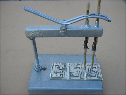
Its like everything the more you use something and be set up for a job the easier it becomes. I once hated the idea of working with SMD but now find it rather quick, and not so bad. The hardest part now is etching the boards to a fine tolerance to fit the chips. Pete. Sometimes it just works |
||||
| Gizmo Admin Group Joined: 05/06/2004 Location: AustraliaPosts: 5185 |
Now thats clever. The best time to plant a tree was twenty years ago, the second best time is right now. JAQ |
||||
| GWatPE Senior Member Joined: 01/09/2006 Location: AustraliaPosts: 2127 |
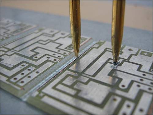
Hi Readers, I have a v1.1 of Pete's 3rd hand smd clamp. I have included a pic of a smd mosfet I had previously soldered by hand. This device has 6pins, and the pins are really close together. I normally just solder all pins and then use wick to remove the excess, as it is almost impossible to solder the pins individually. As Pete, has said, making a PCB with the tollerances for the tiny pads is a challenge. 
This little device is a mosfet I have used on a picaxe for driving a SSRelay. This one has a 20mOhm ON resistance. I use a pair of reverse acting tweezers to place a device under the pin and then guide the pin to the clamp position. I am yet to shim the pin to allow more precise operation, but the little clamp does help with all types of devices. Gordon. PS I have some smd zener diodes, that are 1/3 the size of this mosfet, but I was unable to photograph. These are even a challenge with the clamp. They look a bit like coffee bits in the sugar bowl. become more energy aware |
||||
| VK4AYQ Guru Joined: 02/12/2009 Location: AustraliaPosts: 2539 |
You guys are unreal working with the little suckers, and I like the innovation for clamping, I hadn't seen that even on tutorials, but I will leave them to you guys because I think soldering something the size of a grain of coffee is way beyond me. All the best Bob Foolin Around |
||||
| Downwind Guru Joined: 09/09/2009 Location: AustraliaPosts: 2333 |
[quote]I hadn't seen that even on tutorials [/quote] Thats because it was my solution to a problem and i haven't written the tutorial yet. Aussie backshed engineering for a problem.
Pete. Sometimes it just works |
||||
| Tinker Guru Joined: 07/11/2007 Location: AustraliaPosts: 1904 |
Looking at that picture I can hear the little sucker yelling "OUCHHHH" Klaus |
||||
| Janne Senior Member Joined: 20/06/2008 Location: FinlandPosts: 121 |
Hi, Pete's apparatus for holding the small chip in place seems quite smart. If you don't have a device like that to hold the chip in place, then it's easiest if you first apply solder flux to the pads being worked on. After that, add little solder to the tip of the iron, hold the chip with tweezers, and solder the first pad with the help of the pre-applied flux. A felt-tip pen with flux is the best tool for applying it. If at first you don't succeed, try again. My projects |
||||
Doug Regular Member Joined: 11/05/2010 Location: New ZealandPosts: 41 |
I would have to agree with Glen and Bob. I have enough problems soldering regular sized components, what with old eyes and shaky hands. Let alone something I can't see. It does however, never fail to amaze me just how much the manufactures can fit on something the size of a match head. Doug May The Power Be With You |
||||
| graynomad Senior Member Joined: 21/07/2010 Location: AustraliaPosts: 122 |
I've been salvaging components from dead motherboards lately. I probably get about 200 Rs and Cs off a board, mostly 0603 size. Man they are small, a whole motherboard's worth on the desk looks like I spilt some salt and pepper. BTW, those magnifying headsets from Dick Smith are great. ______ Rob Rob Gray, AKA the Graynomad, www.robgray.com |
||||
| Air Bender Senior Member Joined: 25/01/2011 Location: AustraliaPosts: 206 |
My eye site has being down hill quickly in the last couple of years and i have trouble reading the colour codes on the resisters with a magnaphing glass. My kids got a microscope that conects to the computer, very cheap $25 and works very well. I will be using when it comes time to put together a couple of kits. All the best Dean. |
||||
| Alasdair Regular Member Joined: 12/01/2011 Location: AustraliaPosts: 62 |
Hi all, I think you'd better brace yourselves for more to come, the word I've heard in the industry is that legged discreet components will soon be history, manufacturers of components don't like paying for excess copper that gets trimmed off and board manufacturers love smd. By the time my son learns to solder, I think I'll be giving him history lessons in electronics with the stuff I do. It's amazing to think that 555's and 741's are now obsolete antiques. I too hate making boards for LSI chips, I recently ran over my MP3 player with the ride on mower (accidentally) which wrecked the battery. I busted it open and fitted the still good circuit boards into a jiffy box and glued the display behind a carefully cut hole, I extended wires from the button pads to panel mounted buttons for control, I run a 7805 and a diode to give 4.4v and it works well, but soldering the links (40wires) between the boards was like doing brain surgery on an ant. The wires were about 0.2 mm apart and the pads had a gap of about 0.05mm, almost invisible without big magnification. I ran hot melt over both points after inspecting and testing, I now have the biggest (physically) 8 gig mp3 player in the world, but it's even easier to use. I aso put a TDA2822 amp chip and speaker in the box and now it's even more versatile. I guess I 'un- miniaturized' it. Amc-elec |
||||
| graynomad Senior Member Joined: 21/07/2010 Location: AustraliaPosts: 122 |
[quote]like doing brain surgery on an ant[/quote] He he, that's good. For a while now I've designed boards with SMDs but it was only yesterday that I started actually soldering one (with a hot air station). It was so easy do to it's not funny, a little solder paste and some hot air. Job done. The only hassle I had was removing some PTH LEDs because I put them in backwards, that was a drama. So my thoughts are SMD, bring it on PTH, good riddance Of course SMD makes protoyping difficult, but I seldom (never really) do this, I just make a PCB straight up. ______ Rob Rob Gray, AKA the Graynomad, www.robgray.com |
||||
| Page 1 of 2 |
|||||
| The Back Shed's forum code is written, and hosted, in Australia. | © JAQ Software 2026 |
