|
|
Forum Index : Electronics : Windmill Controller/Charger
| Page 1 of 2 |
|||||
| Author | Message | ||||
| Nehemiah Newbie Joined: 19/10/2005 Location: AustraliaPosts: 8 |
G'day, While looking over your site, I came across the windmill controller/charger. I'm a student at the Australian Science and Mathamatics school and I think that the controller/charger whould make a great school PICAXE project (as I could later use it on my home setup). I have only a few questions that relate to the construction of the circuit.
Where did you obtain these items? I have had a look around the internet, Altronics and Jaycar... Yet no luck. Do you have the specs of these components? As I may be able to find an easy subsitution, or do you know of one? Also relating to the diagram... you have what seems to be a second buzzer connected off the PICAXE (pin 9 and 10 (i think  )). Could you please clarify what this component is (sorry if its a bit noobish). )). Could you please clarify what this component is (sorry if its a bit noobish).
Any other details that I may trip up on? Lastly have you made any changes to the PICAXE program since it was uploaded? Thanks for your help! Keep up the good work! Sam. |
||||
Chris Senior Member Joined: 12/09/2005 Location: AustraliaPosts: 146 |
For the mosfets, any will do, as long as they are N channel, thats if the circuit uses N channel ones. Just try and find a mosfet with the lowest RDS-on figure for maximum effiency and less heat. I would recommend buying some mosfets thru www.oatleyelectronics.com Buy some IRFZ44N's or IRFZ24N, i forget which ones they sell at oatley, but they are cheaper then most places in aus and better then anything jaycar has. As for optocoupler, i think jaycar have them, just not under teh same name: Jaycar have these types MOC3020/MOC3021 OPTO COUPLER IC 4N28/4N25 OPTO COUPLER IC 6N138 OPTO COUPLER IC I used to get caught up on part numbers as well, just try find a equivilant, you dont neccessaryily need teh same, even if features are different. Oatley also sell opto couplers too i think. |
||||
| Nehemiah Newbie Joined: 19/10/2005 Location: AustraliaPosts: 8 |
Yeh, Oatley's is great... I ordered PICAXE-28X MICROCONTROLLER CHIP: (PICAXE-28X) SDP55N03L MOSFET: 30V / 55A (N channel, TO-220 package), 0.0125ohms on resistance. and IRFZ44N MOSFET: 55V / 41A (N channel, TO-220 package), 0.0175ohm on resistance. I'm guessing that the mosfet looking device labled "7805" is a 5V voltage regulator. |
||||
| Gizmo Admin Group Joined: 05/06/2004 Location: AustraliaPosts: 5183 |
Hi Sam. When I built the charger I used whatever was in the junk box. I like to collect stuff :) The power MOSFETS and opto couplers were from a dead UPS. UPS's are a good source of power parts, ie tranformers, relays, etc. Most UPS get thrown out simply because the battery has died. Yeah the 7805 is a 5v regulator. Make sure you use a IC socket on the picaxe, they can be damaged by excessive heat when soldering. Glenn The best time to plant a tree was twenty years ago, the second best time is right now. JAQ |
||||
| Nehemiah Newbie Joined: 19/10/2005 Location: AustraliaPosts: 8 |
I'm still mystified by the piezo speaker look-a-like. |
||||
| Chris Senior Member Joined: 12/09/2005 Location: AustraliaPosts: 146 |
mmm, yeh i see what your talking about nehemiah. You'll have to wait for gizmo's response on that, its probably a warning alarm or something like that. |
||||
| Gizmo Admin Group Joined: 05/06/2004 Location: AustraliaPosts: 5183 |
Thats a resonator. The 28X picaxe chips need an external resonator, the other chips have it built inside. When you order a 28X it should come with the resonator. If not then phone the supplier and ask then for one. I think from memory its frequency is 2MHz, the clock frequency of the microprocessor inside the chip. Hope that helps. It should arive with your chip. Looks like a small capacitor. Glenn The best time to plant a tree was twenty years ago, the second best time is right now. JAQ |
||||
| Gizmo Admin Group Joined: 05/06/2004 Location: AustraliaPosts: 5183 |
Hey if your thinking of building the controller, hold off a week or two. I'm making a few changes. I plan to add a battery current sensor, and want to improve the software. The software is getting pretty tight, there is not a lot of room for variables in the little picaxe, so you need to get clever and reuse variables when ever possible. But I think with some clever code it could even be possible to have trickle charge/boost charge modes, batter dissconnect if the voltages drops too low, etc. I'll keep you all posted. For anyone who has already built the controller, there is a meter display program on its web page. This will let you see the battery voltage on your computer via the serial cable to the controller. http://www.thebackshed.com/Windmill/charger1.asp
Glenn
The best time to plant a tree was twenty years ago, the second best time is right now. JAQ |
||||
| Chris Senior Member Joined: 12/09/2005 Location: AustraliaPosts: 146 |
Wow, thats turning out really nicely dude. Your should start selling them as kits... |
||||
| Nehemiah Newbie Joined: 19/10/2005 Location: AustraliaPosts: 8 |
Lol, Damn!... just started making it! Will it be a modifcation or a compleate re-design? |
||||
| Gizmo Admin Group Joined: 05/06/2004 Location: AustraliaPosts: 5183 |
Just a modification, and an addition. If you have already made the circuit board, it would only involve lifting 2 resistors and adding a couple of components. The current sensor will be a daughter board, based on a 741 op amp and a few resistors. I tested it tonight and it works, so tomorrow I'll start working on the code. Glenn The best time to plant a tree was twenty years ago, the second best time is right now. JAQ |
||||
| Gizmo Admin Group Joined: 05/06/2004 Location: AustraliaPosts: 5183 |
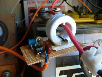
This is the hall sensor daughter board. Its all working, but I want to tidy up the code and draw the circuit diagram before I put the details on the web site. The amp meter has a range of -127 to 127 amps, or -12.7 to 12.7 amps, depenting on how you set it up. The amps is also sent down the serial cable along with the battery voltage, so you can watch the battery V and A on your computer.
Glenn The best time to plant a tree was twenty years ago, the second best time is right now. JAQ |
||||
| Nehemiah Newbie Joined: 19/10/2005 Location: AustraliaPosts: 8 |
That's cool... Hope to see it working! Few more questions... 1. About the illusive 50A rectifier diode... Where did you obtain yours...? I brought 3 50A bridge rectifiers for the AC to DC... however 50A diodes are yet to be found. 2. The mosfets... I'm really worried that what I get won�t work. Could you please make a recommendation? I know they are 33A but that�s the best I can do... This project being built for school over the next week. Will this work? I have four of these on hand. I also have four of these on hand. help. Thanks, Sam |
||||
| Chris Senior Member Joined: 12/09/2005 Location: AustraliaPosts: 146 |
Both your questions are pretty easilily answered. 1. Just buy a couple of 30A rectifiers from jaycar and combine them to make a three phase rectifier. 2. Your first recommendation (the jaycar mosfet) Is okay, but has pretty high on resistance. The second one, is perfect. IRFZ44N are great for price you pay, oatley sell them 3 dollars each so you cant go wrong. Remember, with mosfets you can stack them up, so add maybe another 2 and it will make the circuit more efficient and can handle more current. However dont go over the rating of the PIC output current. The third recommendation wont work, because they are P channel mosfets and you need N channel. You could use a inverter chip but thats more money and more hastle, keep things simple if they already work! I would definately just buy some IRFZ44N or similar to that from oatley. |
||||
| Gizmo Admin Group Joined: 05/06/2004 Location: AustraliaPosts: 5183 |
Its done. Look at the projects/charger page for the updated charger circuit. I still want to document the workings better, give a real description of how the code works, give me a couple of days. But the circuit is working. The LCD display shows battery volts and battery current. Chris is right about the mosfets, just about any N channel power mosfet will work. And to get the 50amp diode, connect some lower amp diodes in parallel. My diode came from an old Telecom telix machine ( remember them? ). Glenn The best time to plant a tree was twenty years ago, the second best time is right now. JAQ |
||||
| Nehemiah Newbie Joined: 19/10/2005 Location: AustraliaPosts: 8 |
All good so far... one last question. With the PICAXE timer, of the three pins, which two connect to the chip? |
||||
| Gizmo Admin Group Joined: 05/06/2004 Location: AustraliaPosts: 5183 |
From memory, the middle pin is connected to ground ( -ve ), and the other two pins connect to the chip, dosn't matter which way around.
Glenn The best time to plant a tree was twenty years ago, the second best time is right now. JAQ |
||||
amiklic1 Newbie Joined: 15/10/2005 Location: CroatiaPosts: 2 |
Hello folks. I'm back to this forum after a while, and can see things have changed. I am in the process of building the controller, but now I have to change few things. I made real pcb for this project, and when I change it and test the circuit, maybe it would be ready for release. I hope so. Go on, this is a he.. of a project. Maybe to incorporate mppt into this? It's a great thing, too.
Is it too late for something good to be done? I'll try anyway! |
||||
| Gizmo Admin Group Joined: 05/06/2004 Location: AustraliaPosts: 5183 |
Glad to see your getting somewhere with the controller. MPPT? Hmm, might need some more processing power for that. Most of the code in the picaxe is just to drive the display, maybe have two chips, one to drive the display, and one to do the smarts stuff like MPPT, charging cycles, etc. I think there is a little bug in the code, havn't looked close at it yet. When I adjust the charge/load voltage, it goes into forced load mode instead of normal charge mode. Its only a minor thing, but I should have a look and sort it out. Glenn The best time to plant a tree was twenty years ago, the second best time is right now. JAQ |
||||
| Chris Senior Member Joined: 12/09/2005 Location: AustraliaPosts: 146 |
What method of regulation do you use? Is it PWM? If it is, is that hard to program? Im looking at doing a similar thing with a PIC for a different project. |
||||
| Page 1 of 2 |
|||||
| The Back Shed's forum code is written, and hosted, in Australia. | © JAQ Software 2026 |