
|
|
Forum Index : Electronics : 1uf caps on 7 phase
| Author | Message | ||||
Highlander Senior Member Joined: 03/10/2006 Location: AustraliaPosts: 266 |
G'day fella's, I made a different neo rotor with the magnets placed away from the stator. This has a start cogg of 450 ml Without caps it's total current is 17.5 amps into a 12v battery 7 by 1 uf caps were placed where the star normally goes, 1 between each phase and one between 1 and 7 open circuit results 24v @ 285 rpm 30v @ 374 rpm 45v @ 534 rpm 75v @ 974 rpm When a load is connected the highest current is 10 amps @831 rpm I then shorted out the caps, which gives a star. Total current rose to 17.5 amps open circuit results 24v @ 299 rpm 30v @ 354 rpm 45v @ 537 rpm 75v @ 874 rpm I tried placing caps on all three stars initially and had 0 amps with a load so 2 sets were taken off and the above tests were done. Can anyone explain why the current falls so much with the caps? And what's the use of them if so much current is lost? 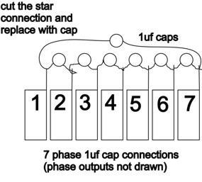 Central Victorian highlands |
||||
| KiwiJohn Guru Joined: 01/12/2005 Location: New ZealandPosts: 691 |
Hi, you should try and find that article by Dr Chalko where he explained the purpose of the caps. |
||||
| Highlander Senior Member Joined: 03/10/2006 Location: AustraliaPosts: 266 |
Hi John I re read chalko, he had quite different results to me, both watts and volts were higher on his tests. But he was using 3 phase. Is this not suitable for the 7? Central Victorian highlands |
||||
| KiwiJohn Guru Joined: 01/12/2005 Location: New ZealandPosts: 691 |
HI, Highlander, the thing about those capacitors is that they are part of "tuning" the circuit so they need to be of the right size. I think in Chalko's paper he mentioned something about the optimum size capacitor. I certainly am not able to calculate what might be better but I can give you a couple of clues that might help you. Firstly, although you have seven phases you really only need to measure one to find if you are on the right track. Here is what I think would be a good way to go, but I should not pretend I am any sort of expert on this subject! 
Begin by measuring the output of just one phase making your connection between the common star connection and one phase terminal. Measure first without any capacitor, then try just one capacitor between the phase and the star connection, next put two of your capacitors in parallel with each other, connected in this way you have twice the capacitance of one. Lastly, put two capacitors in series, connected in this way you have only half the capacitance of one. I think the principles of 3 phase will apply to 7 phase too, my feeling is that less capacitance will be the ideal but if you do those tests you might get some clues. Good luck! John |
||||
| Gizmo Admin Group Joined: 05/06/2004 Location: AustraliaPosts: 5012 |
Hi Highlander. Just check the article for the connection he used. I got the impression he meant a capacitor across each phase, but I could be wrong, like this... 
and the star connection is left intact. Glenn The best time to plant a tree was twenty years ago, the second best time is right now. JAQ |
||||
| Highlander Senior Member Joined: 03/10/2006 Location: AustraliaPosts: 266 |
Hey Glen his description is a bit vauge, it might be either. 
That drawing looks nice but bear in mind I'm an electrical imbecile, I think you mean a cap between the phase outputs before they reach the bridge rec? Anyway I did the tests (before I read your input) with phase 1 and 2 connected to a bridge rec. Std star config 4.5a (loaded) 2 1uf parralell 2.5a 2 1uf series 2.8a 3 1 uf series 2.8a Got me buggered. I'm putting my mill up in the morning so I've run out of time to bugger around with it. I'll put on my std stator and just get some amps flowing. Thanks for the all the help guys Central Victorian highlands |
||||
| KiwiJohn Guru Joined: 01/12/2005 Location: New ZealandPosts: 691 |
We should be able to calculate the optimum capacitor size from the inductance of the stator. I will have a look tonight and see if my brain is up to the task. |
||||
| KiwiJohn Guru Joined: 01/12/2005 Location: New ZealandPosts: 691 |
OK, I give up on this one, too hard for this old brain! If the caps dont bring any improvement then leave them off I guess! |
||||
Megawatt Man Senior Member Joined: 03/05/2006 Location: AustraliaPosts: 119 |
G'day Highlander, Gizmo's connection is right. Megawatt Man |
||||
| Highlander Senior Member Joined: 03/10/2006 Location: AustraliaPosts: 266 |
Hey Mega, thanks, does that drawing mean a cap between the phase outputs before they reach the rectifier? I put my mill up, I think I de-tuned it a bit much, the max output is 17.5a (450ml start)and it has no problem reaching it at all, even in light wind. Ply blades work well. I'll leave it for a while to see when it furls and add more neo's when I pull it down. So thanks Glenn for giving me such a fun project  and thanks to everyone that helped. and thanks to everyone that helped.
I made a gen with a honda 3.5hp with a belt running a F&P I'll test the caps out on that, a bit easier to solder on the ground 
My inverter will run the a/c, I haven't tested the draw yet but I'll probably need the gen on hot days to keep the batteries up. This started as a tinkering project, but now it's actually very usefull. Central Victorian highlands |
||||
| Gizmo Admin Group Joined: 05/06/2004 Location: AustraliaPosts: 5012 |
Hi Highlander. Yeah the cap between each phase before the rectifier. 17.5 amps is a good output, respectable figure. Into 12 volts thats over 200 watts, sounds like those ply wood blades are working ok. Glenn The best time to plant a tree was twenty years ago, the second best time is right now. JAQ |
||||
| Megawatt Man Senior Member Joined: 03/05/2006 Location: AustraliaPosts: 119 |
G'day Highlander, Again Gizmo has it right. Megawatt Man |
||||
| Megawatt Man Senior Member Joined: 03/05/2006 Location: AustraliaPosts: 119 |
Hello Highlander and other blokes who are interested in this point. There are a couple of reasons for the poor performance compared with Dr Chalko's unit. First, some explanation is necessary. If you look at the graphs that Gizmo has put on the site for the output voltage waveform for three phase and seven phase connections you'll see that the top of the graph is a pretty bumpy thing. Each bump shows the voltage output for one particular coil when the magnets are directly exciting it. When the voltage reduces because the magnets have very nearly passed the coil, the next coil starts to increase its voltage output. What happens is that the current that was flowing out into the load from the first coil stops when the second coil develops a higher voltage and it in turn starts to supply the current. The current actually switches from one coil to the next. Now when you switch electric current in practical devices, the magnetic field and the electric field effects object to the rapid changes and try to keep the current going. They then starts a rapid exchange of energy between the magnetic field that is collapsing in the coil and what is called "stray capacitance". Yes, there is such a thing. Even though the coil looks exactly like a coil, between each turn of the coil there is a small but influential capacitance. It's like you connected a tiny capacitor between each adjacent turn of the coil. Capacitors store energy for a very short time in an electric field, just like inductors store it in their magnetic field. When the magnetic field collapses because the current drops, it cuts the turns of the coil it was in and generates a voltage and therefore a current that flows into the tiny capacitors. When the magnetic field has stopped collapsing, there is no voltage generated to drive the current into the tiny capacitors, so it comes out again and cause a current in the coil, that causes a magnetic field to build up until the capacitors are empty and the same thing happens again and again until the losses cause the original energy to dissipate. (This phenomenon is known to comms blokes as "Ringing"). Each combination of inductance and capacitance have a natural or "resonant" frequency at which this happens. Because the stray capacitance is small, the frequency for our F&Ps is very high, too fast for the iron to change magnetisation readily, so the energy is lost in heat in the core. Now when you use a 7 phase arrangement, the changeover between coils occurs 7/3 times more often that in a 3 phase winding, so you can expect 7/3 times the losses. So that's one of the reasons. To overcome the high frequency energy exchange at switching, Dr Chalko recommended fitting capacitors. What they do is completely overcome the high frequency tendency to ringing by making the available capacitance much greater, bringing the frequency of the energy exchange down into the range that allows the iron to magnetise and demagnetise as usual and this does not absorb so much of the energy. So it can produce efficiencies. But there's a down side too. When we connect the capacitors between the star points, some current flows from the windings into them. Because the windings are not perfect in that they have resistance as afundamental electrical proerty, this additional current causes heating and that is a direct loss to the output. So that's another reason. There is one other reason for Dr Chalkop's losses being less than we want. His work aimed to produce an alternator that was efficient at around 100 watts, to suit small hydro installations. He did experiment up to about 350 watts. To get rid of a lot of his iron losses, because he was looking at a small output, he cut off half of the iron - every second pole! That's not what we are looking for. We need a machine that can output about 1 kW. It turns out that there is a delicate balance between how much capacitance you need to reduce losses in the iron core and avoid increasing losses in the coils. Hope this is of assistance. Megawatt Man |
||||
| Highlander Senior Member Joined: 03/10/2006 Location: AustraliaPosts: 266 |
Hmmm, thanks Megawatt, it appears I always ask or tackle difficult things. I'll read this a few times to take it in properly, but like Kiwijohn said earlier it's about tuning the circuit, a bit like tuning handloads for a new rifle. Thousands of variables and many that work well, finding the perfect one is elusive. Central Victorian highlands |
||||
