
|
|
Forum Index : Electronics : circuit for 7 phase star/delta switch
| Page 1 of 2 |
|||||
| Author | Message | ||||
Pt w/field Matt Senior Member Joined: 24/02/2006 Location: AustraliaPosts: 105 |
hi all worked out a circuit using 14 car relays or 7 dpdt with low pull in current, i got 268 watts with it on my petrol engined test bench and dropped 2 amps on low revs using a 7p 2p 80 series stator wired in star. ill get highlander to post the circuit once ive tested it matt down south |
||||
| domwild Guru Joined: 16/12/2005 Location: AustraliaPosts: 873 |
Great stuff! When you are ready! Why that many relays, one car horn relay can handle 30 or so Amps? Taxation as a means of achieving prosperity is like a man standing inside a bucket trying to lift himself up. Winston Churchill |
||||
Highlander Senior Member Joined: 03/10/2006 Location: AustraliaPosts: 266 |
Well, I don't have the diagrams or pics yet but if the 3 phase needs 6 wires for a star delta, then a 7 phase would need 14 wires for a star delta, I think. Is that what you've done Matt? Central Victorian highlands |
||||
| Pt w/field Matt Senior Member Joined: 24/02/2006 Location: AustraliaPosts: 105 |
hi all tried 7 phase 8o series 7p 2p wiring in star and got 11 amps @ 25.6 volts great it works took it of the 5hp test bench undid the star connections on the wires for star and rewired for delta,back on the rig and no output in 24v mode tried 12 v still nothing open circuit 3v soo do you still want the circuit for 7 phase star/delta switching? will check with a sparky mate and see if ive done something wrong,i wired it as 7 coils in a circle with the ends of the coils joining from one to another and took the phases out at each join is that right?and can 7 phase delta work like 3 phase delta [good for top end power like a big cam in a car]?why so many relays cause we are dealing with 4 more phases,some 3 phase s/d switches use 3 some 6 matt down south |
||||
Gill Senior Member Joined: 11/11/2006 Location: AustraliaPosts: 669 |
Yes Matt, dont give up on 7 phase star/delta just yet, in spite the disappointing first result. It can be done but I don't have the time right now to draw it up. Recheck all connections and coil orientation and please do post your switch circuit 
was working fine... til the smoke got out. Cheers Gill _Cairns, FNQ |
||||
| domwild Guru Joined: 16/12/2005 Location: AustraliaPosts: 873 |
Matt, Thanks for that. At least those relays are cheap. Keep persisting! Regards, Taxation as a means of achieving prosperity is like a man standing inside a bucket trying to lift himself up. Winston Churchill |
||||
| Pt w/field Matt Senior Member Joined: 24/02/2006 Location: AustraliaPosts: 105 |
hi all posted the circuit to hilander today so he should get it by weeks end,i included a circuit for the way i wired up the straight delta to test the gain maybe someone get work out what ive done wrong. will have a go at a 100 series and see what that does. rechecked 80 series wiring and done a ohms test and it came out fine,showed it to a sparky mate and he couldnt fine any faults,on the test bench theres no load on the motor even when the battery leads are shorted together and no heat in the stator,the stator was wired in halves for testing on my exersize bike might test one half at a time and see. matt down south |
||||
Megawatt Man Senior Member Joined: 03/05/2006 Location: AustraliaPosts: 119 |
G'day gentlemen and ladies if there are any. I guess your star arrangement was 6 coils in series for each phase. The start of one coil would be connected to the finish of the next and so on all the same for each phase, so that the voltage generated in each coil is additive to the next. The delta connection should use the same groups of six, still all connected in series, but in the same way as the series connections, the start of one group of 6 needs to be connected to the finish of the next group and so on, until the start of the last group connects to the finish of the very first group. They will then all be connected in a ring. The output connections are to each of the points where start of one group connects to the end of the next, so there will be 7 output cables to go to the rectifiers. Megawatt Man |
||||
| Gizmo Admin Group Joined: 05/06/2004 Location: AustraliaPosts: 5181 |
You know, I wonder if delta 7 phase would work at all. I have a feeling we are missing something, and the obvious connection is not the way to make it work. I need to have a think about this. Glenn The best time to plant a tree was twenty years ago, the second best time is right now. JAQ |
||||
| brucedownunder2 Guru Joined: 14/09/2005 Location: AustraliaPosts: 1548 |
Just reading and thinking --why no results and "no load" ..hmmm. Remember,, you must use the NEW version ROTOR when doing this test. Tell you why I say this,,, I tried the 7 phase re-config and screwed on an original style Rotor and found out it did not cogg and did not put any volts out also --completly mis-matched. So, maybe..... got the new stator (.6mm ) re config to 3/4 pole with a new Rotor-- Even though we have had very little wind lately ,yesterday I saw it running fast ,raced into check the o/p --dismal--- around 4 Amps into the 27V bank. So maybe these new Stators might need "re- winding with the original .8mm wire -big job ,. Has anyone had a go at re-winding ? Would be fairly easy if we could wind those plastic bobbins on the pole "Fingers" and then slip them down into place--just dreaming ,but it might work ?? Bruce Bushboy |
||||
| Pt w/field Matt Senior Member Joined: 24/02/2006 Location: AustraliaPosts: 105 |
hi bruce i disagree with your statment of no cogging with 42 pole stator and old type hub thats built in thats why f&p changed the shape of the magnets to a arrow shape with that said yeah i was using the latest type rotor to match 7 phase rewire. might try to figure out a series/paralel switch in 7 phase like innovation is doing and see wtat that does matt down south |
||||
| Highlander Senior Member Joined: 03/10/2006 Location: AustraliaPosts: 266 |
This is something Matt mailed me and I scanned for him. 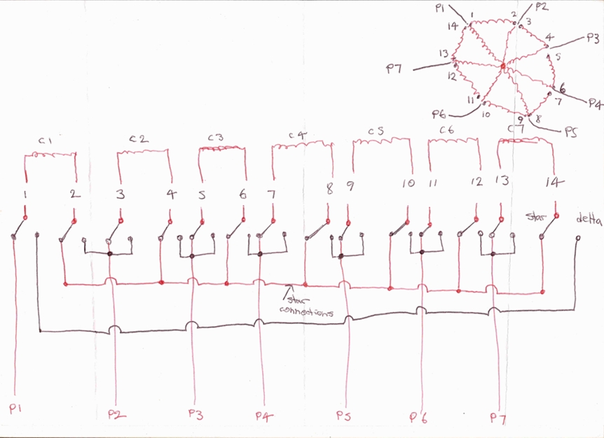 Central Victorian highlands |
||||
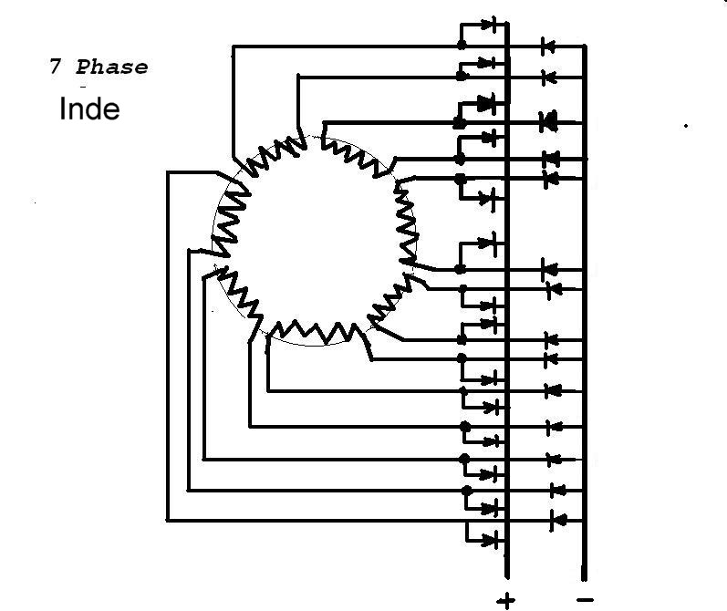
| Gill Senior Member Joined: 11/11/2006 Location: AustraliaPosts: 669 |
Matt Thanks for the circuit. It will suit my solution . Sorry I havn't had time to draw this up earlier. We all know of Star and Delta, but there is a third. I am going to call it Inde (Independant). Now I'm sure it's been thought of before but I reckon it's never used because it needs more wires (same as Star/Delta)and twice as many diodes. I also believe Inde will give the same characteristics as Delta in spite of the extra diodes. If an F&P is made for Inde it can easily be connected/switched to Star or Delta. Sorry I can't do the beautiful graphics but at least the idea is out there. I have a Inde wireing diagram for the stator too, but sorry the scanner is on the fritz. 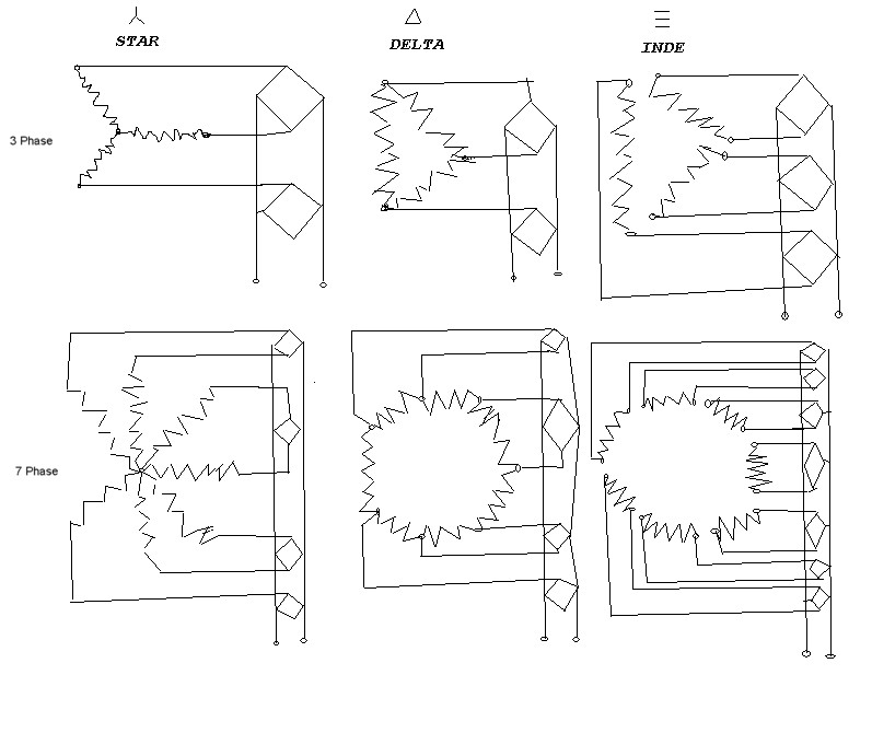
 was working fine... til the smoke got out. Cheers Gill _Cairns, FNQ |
||||
| Pt w/field Matt Senior Member Joined: 24/02/2006 Location: AustraliaPosts: 105 |
hi Gill thanks for the tip on getting my meter to read frequency done low it worked a treat,ill give the inde wiring a bash and see if theres some more top end power to be had! so far 80 series wired 7p3pole seems the go for 24v on the test bench with a low cut in speed,100 series wired the same cuts in at 450 revs and would suit a fast mill ,it also has the most power at 380w @1000 rpms verses 250w for the same revs for the 80 series. matt down south |
||||
Robert_VK2BBR Regular Member Joined: 31/12/2006 Location: AustraliaPosts: 67 |
Hi Gill Thanks for the drawings. regards robert ps I saw another system for conecting 3 phase alternators that i think used an extra diode at the 'neutral point (star conection i think. I will se if I can find it again. 1555 W grid connect system since Jan 08 both vehicles running on modified, used vege oil. |
||||
| Pt w/field Matt Senior Member Joined: 24/02/2006 Location: AustraliaPosts: 105 |
hi all tried Gills INDE wiring setup and it would suit a very high speed mill,it t was tested with a 100 series 7p 3pole stator and starts charging at 860 revs and 5 watts output,at 1ooo revs 50 watts and 1115 revs 128 watts.with star wiring i got 350 watts at 1000 revs soo has any body got some more ideas or do we stick to star on 7 phase setups? matt down south |
||||
| Robert_VK2BBR Regular Member Joined: 31/12/2006 Location: AustraliaPosts: 67 |
an alternative is two phases in series per diode bridge, twice the voltage twice the fun? 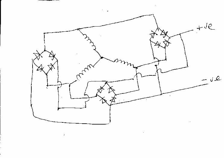 1555 W grid connect system since Jan 08 both vehicles running on modified, used vege oil. |
||||
| Gill Senior Member Joined: 11/11/2006 Location: AustraliaPosts: 669 |
Sorrry Robert, I disagree with your proposed circuit, or at least that it puts two phases in series and doubles the voltage. What I see is each phase going through 2 diodes in parallel to double the current carrying capacity of the rectifier. The rectifier supplied with some ecnovision kits are like this. The diference is only in wireing. On your circuit your parallel diodes are on seperate bridge rect, whilst econivision is very neat paralleling diodes on the same bridge. 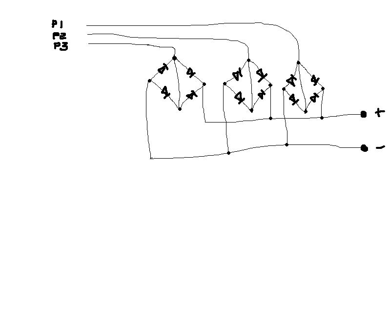
But still fun for sure. was working fine... til the smoke got out. Cheers Gill _Cairns, FNQ |
||||
| Pt w/field Matt Senior Member Joined: 24/02/2006 Location: AustraliaPosts: 105 |
hi Rob yeah but im running 7 phase and not 3, if i was running 3 phase i would use a star/delta switch and get some real power. matt down south |
||||
| Chipboy Newbie Joined: 13/12/2006 Location: AustraliaPosts: 16 |
Hey Rob, you know full well I told you its only 1.73 (sqrt3) times the single phase voltage not twice! Might well be lots ie > 2 of fun though! Matt Wind wannabe |
||||
| Page 1 of 2 |
|||||
| The Back Shed's forum code is written, and hosted, in Australia. | © JAQ Software 2026 |
