
|
|
Forum Index : Electronics : Simple dump circuit
| Author | Message | ||||
| South Easter Newbie Joined: 18/06/2007 Location: Posts: 36 |
Hello all. I want a simple circuit to switch on a dump load at a preset voltage. I don't know much about electronics, but have tried to design something as follows. Any comments or suggestions would be much appreciated! Thanks in anticipation. 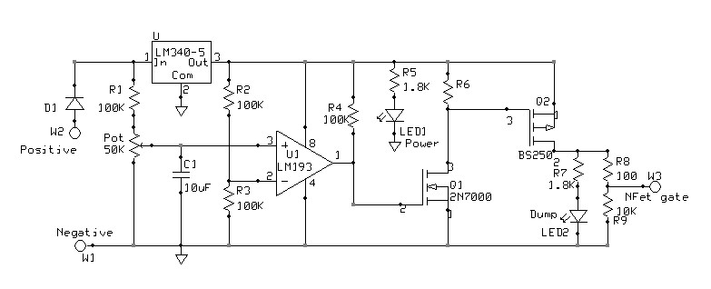 South Easter http://windpower.org.za |
||||
| GWatPE Senior Member Joined: 01/09/2006 Location: AustraliaPosts: 2127 |
Hi South Easter, I have just finished some testing of Gil's code and my own for an AXE-08M. I will post on another thread, not sure which one, probably PWM-Regulation_ideas cheers, Gordon. become more energy aware |
||||
Gill Senior Member Joined: 11/11/2006 Location: AustraliaPosts: 669 |
G'day South Easter, What do you mean don't know much? The circuit mostly looks OK with the exception there is no positive feedback to give some hysteresis for switching. RossW has posted a proven simple circuit much like yours in this thread here I cannot seem to open the pic of his circuit. If you have the same difficulty, give Glenn a shout as sometimes the gremlins have a wee party. was working fine... til the smoke got out. Cheers Gill _Cairns, FNQ |
||||
| GWatPE Senior Member Joined: 01/09/2006 Location: AustraliaPosts: 2127 |
Hi South Easter, A word of warning re- driving a mosfet. Most power mosfets require a gate voltage of 12-15V to turn on hard. Only drive logic level devices from a 5V rail. cheers, Gordon. become more energy aware |
||||
| South Easter Newbie Joined: 18/06/2007 Location: Posts: 36 |
Thanks for the feedback. Here is a modified version which is intended to drive the fets harder. 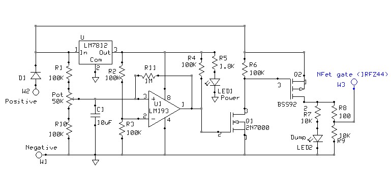 South Easter http://windpower.org.za |
||||
Highlander Senior Member Joined: 03/10/2006 Location: AustraliaPosts: 266 |
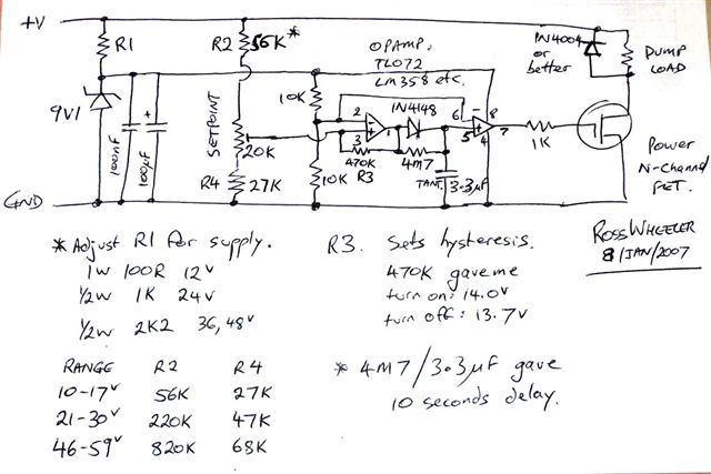
This is the one RossW designed. Central Victorian highlands |
||||
| South Easter Newbie Joined: 18/06/2007 Location: Posts: 36 |
Thanks Highlander! I will study that circuit... In the meantime I had reworked a bit as below. Its skips out the small Nfet by switching inputs to the comparator - thanks again for your comments. Also, this way the output of the comparator is floating, and so I assume draws minimal current when the dump is off. I have chosen the resistors large in order to minimize quiescent power use - I hope not too large? 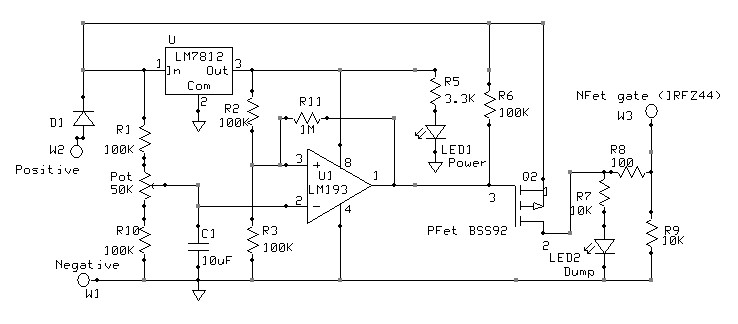 South Easter http://windpower.org.za |
||||
| GWatPE Senior Member Joined: 01/09/2006 Location: AustraliaPosts: 2127 |
Hi South Easter, I have just checked out some of your photos on your site. Good effort. I made my genny by hand as well, but completely different design. A few observations. Axial flux designs suffer badly from eddy current losses within the wire, heating up the wire. I see you are using 1 mm wire and lots of turns per phase. whenever you have a conductor placed in a rotating field, eddy current is developed in all the metal the is aligned with the direction of rotation. This causes the additional heating that can burns the coils at high power levels. The principle is used in magnetic resistance on an excercise bike. In my design I was able to eliminate this additional heating by having wire specially made to my specification by a company in Califormia. This was 15 years ago. I have just read some more of your text and looked more closely at the photos. You have a very large air gap. What dia rotor? Trying to estimate expected output power from your mill. Your figures seem low, but it may be a result of small blade dia. The air gap between the magnets in my genny is 3mm. Only parts of the wire are in the gap, with 0.5mm air either side. I have a 2m dia rotor with 3 blades and I have measured 455W into a 24V Pb acid battery in 10m/s wind and the mill was in full furl. The aluminium tubes that you used to form the coils should also be removed. On the topic above. What voltage are you now using. I see that you have made some of your own batteries 6V, and have a mixture of other batteries. Some of your ccts indicate a 24V system. I see you have modified to use a 12V reg, reversed the logic and included some positive feedfack. What voltage can the comparator withstand on the output? Is it an open collector output? Good luck with your ideas, cheers Gordon. become more energy aware |
||||
| South Easter Newbie Joined: 18/06/2007 Location: Posts: 36 |
Thanks GWat!! Specially made wire, wow. What was different about your spec that a standard wire ddnt work? The air cap is 1mm clearance plus 8mm stator plus 1mm clearance. I struggle to get the rotors 100% true becasue of the bearings I use, and so the 1mm is a bit bigger than I would like it... I think the lower power is partly due to the magnets - they are a bit small, are low grade (N35 I think) and have suffered a lot by being banged around. I plan to try and find some aout 25x50x10mm N40's next, but am struggling to find a good source. The aliminium tubes are removed - perhaps thats not shown well on the site. I use 24V, but would like the circuit to be usable for 12V by cahnging a resistor or two. The 293 is open collector as far as I know. That lets me add the test switch as per the latest version below. Thanks again for taking time to make your comments. 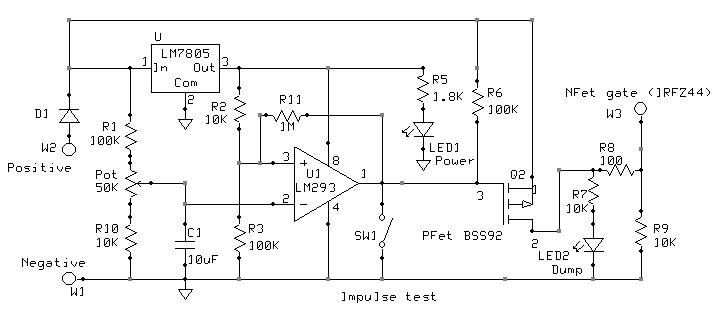 South Easter http://windpower.org.za |
||||
| GWatPE Senior Member Joined: 01/09/2006 Location: AustraliaPosts: 2127 |
Hi South Easter, you have changed R2 to 10k. The 1M positive feedback will have little effect now. I could not buy the wire in Australia, so I sourced overseas. This was pre internet like we know it now. The wire I used has 2 layers of cotton insulation. I still have not been able to source a local supply and have lost details of my original purchase. I do not have enough wire left to do much with, so my genny is a one off. You are saying there is a 10mm air gap between the magnets. This will reduce the power significantly, but this will also reduce the eddy currents as well. Not all bad. You may want to place a zener gate voltage protection across R9 and increase the value of R8. I do not drive a mosfet this way, but this will work for ON/OFF, very low frequency switching. good luck with a prototype. cheers, Gordon. become more energy aware |
||||
| South Easter Newbie Joined: 18/06/2007 Location: Posts: 36 |
Great thanks! So I change R11 to 100K? And change R8 to 500Ohm(?) and add a 30V(?) Zener across R9. I am worried from your comment that I am driving the mosfet the wrong way... could you perhaps mention a better way? For a dump load, the frequency may be quite high. Unfortunately my knowledge doesn't extend to being able to work out the hysteresis or frequency under various conditions. About the airgap.. I was under the impression that 10mm was quite small. If the stator gets too thin (like 5mm?) then it is not very rigid, and also there is not much space for copper... What air gap do you work with? South Easter http://windpower.org.za |
||||
| GWatPE Senior Member Joined: 01/09/2006 Location: AustraliaPosts: 2127 |
Hi South Easter, It is not as simple as that. For reliability the FET gate should be about Max 18V. Work out the series resistor R8 to give a couple af mA at the Max voltage you would expect. To reduce oscillation frequency adjust the filter cap C1 to give a time constant of about 2 seconds. somewhere between 22 & 47uF. The feedback resistor is chosen to select the hysterysis voltage amount. I would use trial and error, but 100k is a start. I prefer to use SSRelays for slow switching speeds. Most of my designs are now PWM ccts. The designs are too complicated to explain here. I did describe the air gap above. The air gap on my genny is only 3mm. This is the gap between the rotating magnetic field where the copper coils are. I have only 0.5mm betweem the magnets and the copper. You see I have very little copper and hence very low resistance. Careful design allows a rigid construction. My stator is equivalent to a porous sheet of copper 2mm thick with strong circular reinforcing rings 10mm thick with a combined 8mm thick mounting plate. Most of the active areas are either magnetic or copper. I could not afford segmented magnets, so the square magnets have a segmentation gap around the outside edge, but touch each other on the inner ring. There are only segmentation gaps at the outside edge between the coils. The magnetic field is completely closed. This design is why my genny produces close to a square wave output. If I had segmented magnets, the power output could be 10% higher and the waveform a near perfect square wave. I have to rectify each of the four phases individually in a delta type arangement. My genny is most efficient spinning at high speed. The windings present about 0.25ohms series resistance. Only at high output power at low rpm does the efficiency drop to around 90%. At the 100W power level as a mill, efficiency is around 97%. I know that during testing at 3000rpm, the output was over 300V at 15A with only 65W winding loss. This is the primary benefit of an ironless design at high rpm. I think this equates to over 98% efficiency. The effective rectifying frequency would be around 550Hz You can probably see that a direct drive mill does not utilize the features of my genny design to the maximum. Would be good for hydro though. Anyway, this is OFF the topic. I hope the cct suggestions help you. Cheers, Gordon. become more energy aware |
||||
Bryan1 Guru Joined: 22/02/2006 Location: AustraliaPosts: 2039 |
Eh Gordon if you need a local supply for magnet wire just holler, the company I work for also own a motor re-winding wholesaler and you tell me what size and weight you want and I'll find the price for you. Cheers Bryan |
||||
| GWatPE Senior Member Joined: 01/09/2006 Location: AustraliaPosts: 2127 |
Hi Bryan, Thanks for your offer. I know the wire type is available overseas still. The rewinding wire supplier in Adelaide I use is O'Briens. I know the CSIRO had similar wire made for a solar car motor, but it wasnt suitable to make ny coils. I don't have the funding or capital reserves like the CSIRO to go chasing. Each coil of my stator took over 1 hour to wind x44 coils. The coils are interwoven with adjoining phases and there is no support for the coils prior to final moulding. Both ends of the wire enter the coil from the outside. On most coils one end starts in the centre and the coil is wound to the outside. There is no room between the magnets in my design to bring the wires from the centre of the coil out, to the terminals. When you build up the layers on a coil, the crossing back and forth wastes space. I was able to fill this with more wire with my design. The terminals are inside the rotor and the wires come out through the hollow aluminium shaft. The rotor completely encloses the stator. The genny cannot be disassimbled without special tools. I really do not want to build another genny by hand anyway. I sold my lathe and Milling machine when I moved house. My electronics projects keep me pretty well occupied now. I still even get time to take my gliders out to go flying. High performance models of my own design. cheers, Gordon. become more energy aware |
||||
| mitchie Newbie Joined: 31/07/2007 Location: Posts: 8 |
Hi South Easter - just wondering where you are located - Im also from the south east |
||||
| South Easter Newbie Joined: 18/06/2007 Location: Posts: 36 |
Hi Mitchie. It refers to the summer wind here, the South Easter. I am in South Africa, Cape Town. South Easter http://windpower.org.za |
||||
| The Back Shed's forum code is written, and hosted, in Australia. | © JAQ Software 2026 |
