Notice. New forum software under development. It's going to miss a few functions and look a bit ugly for a while, but I'm working on it full time now as the old forum was too unstable. Couple days, all good. If you notice any issues, please contact me.
irishron40 Senior Member Joined: 22/09/2014 Location: IrelandPosts: 254
Posted: 02:21am 25 Jun 2016
Copy link to clipboard
Print this post
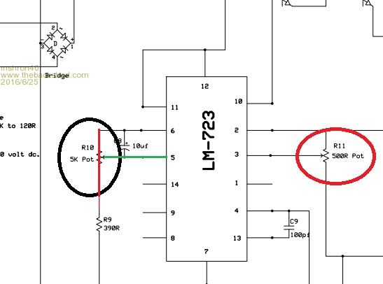
hi. im nearly finished my power supply , but am a bit confused how to connect potentiometers.
am I right to think that the potentio meter be fitted with middle leg onto red line and outerleg to green line?
thank you
ronEdited by irishron40 2016-06-26
irishron40 Senior Member Joined: 22/09/2014 Location: IrelandPosts: 254
Posted: 12:09pm 25 Jun 2016
Copy link to clipboard
Print this post
I am a bit supprised that after 30 views no one knows the answer to my question.
I am fairly new to electronics , so a simple thing to most would be complicated to me.
ron
Madness Guru Joined: 08/10/2011 Location: AustraliaPosts: 2498
Posted: 12:24pm 25 Jun 2016
Copy link to clipboard
Print this post
Middle leg is the one with the arrow in the diagram and is the one that moves.There are only 10 types of people in the world: those who understand binary, and those who don't.
jincamty Newbie Joined: 10/07/2011 Location: New ZealandPosts: 21
Posted: 12:37pm 25 Jun 2016
Copy link to clipboard
Print this post
Hi Ron, You should have three legs on your pot. The middle one will be the green line and the outer two will be each end of the red line. Just Google potentiometer wiring, there are lots of images to describe how.
Just remember some pots are not linear. ie the rate of change of resistance changes.
Cheers Cam.
irishron40 Senior Member Joined: 22/09/2014 Location: IrelandPosts: 254
Posted: 12:51pm 25 Jun 2016
Copy link to clipboard
Print this post
i wasnt sure. thank both for your help. this will get me to finish my power supply.
ron
irishron40 Senior Member Joined: 22/09/2014 Location: IrelandPosts: 254
Posted: 12:33pm 26 Jun 2016
Copy link to clipboard
Print this post
i had a look. but like to also include fine tune potentiometer for voltage and on the current control
they show a 5k pot for voltage and 500ohm for current limiter.
what size should the fine tune pots be and also what way are they wired in series. cant seem to find a diagram on google.
thank you.
ron
Madness Guru Joined: 08/10/2011 Location: AustraliaPosts: 2498
Posted: 12:37pm 26 Jun 2016
Copy link to clipboard
Print this post
I suggest you have a good read of this page it will answer all your questions.
http://www.instructables.com/id/How-to-use-Potentiometer-Arduino-Tutorial/There are only 10 types of people in the world: those who understand binary, and those who don't.
irishron40 Senior Member Joined: 22/09/2014 Location: IrelandPosts: 254
Posted: 01:20pm 26 Jun 2016
Copy link to clipboard
Print this post
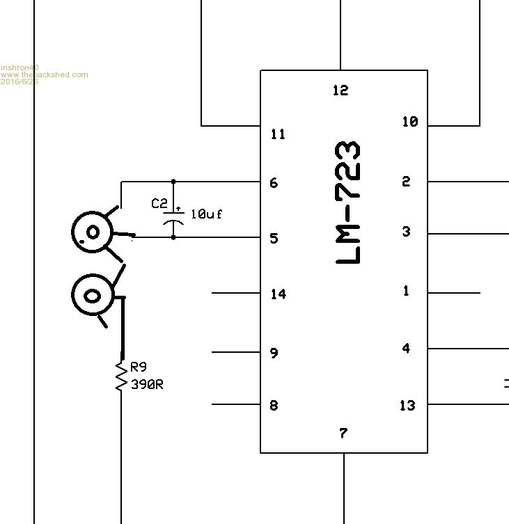
.i read that link. but it doesnt say anything about connecting pots in series. and what vallues. is the way i drawn the 2 potentio meters the right way to wire them to archief course and fine tuning? and can they be both 5k pots?
Edited by irishron40 2016-06-27
MicroBlocks Guru Joined: 12/05/2012 Location: ThailandPosts: 2209
Posted: 08:58pm 26 Jun 2016
Copy link to clipboard
Print this post
You can use a precision trim pot for fine tuning, that is their purpose. They are available in models that have a have lot more turns allowing very fine adjustments.Edited by MicroBlocks 2016-06-28Microblocks. Build with logic.