
|
|
Forum Index : Electronics : CLICK nightlight torch repair
| Author | Message | ||||
Dingdoc Regular Member Joined: 23/09/2009 Location: AustraliaPosts: 76 |
Hi all It's been quite some time since I last posted on the forum but I have been regularly reading most of the contributions. Recently I was asked to see if I could fix a 'Click' nightlight/torch unit which had stopped working. It has an inductive mains charger cradle which holds the light unit and keeps its lithium battery charged until needed. It seems that the electro filter capacitor in the charger dropped its bundle causing the emitter resistor in the oscillator for the coil to overheat and burn out. My problem is that the resistor is now black and grey with no colour bands so I have no idea of its value. I am reluctant to try various values as the charger circuit is at potentially mains voltage and the value is probably quite critical due to significant load changes when the torch unit is removed and replaced. I have traced out and attached the charger transmit circuit and included a couple of photos in the hope that someone will either have one of these and can have a look inside or otherwise be able to deduce the value required for the cooked R4. Thanks Trev 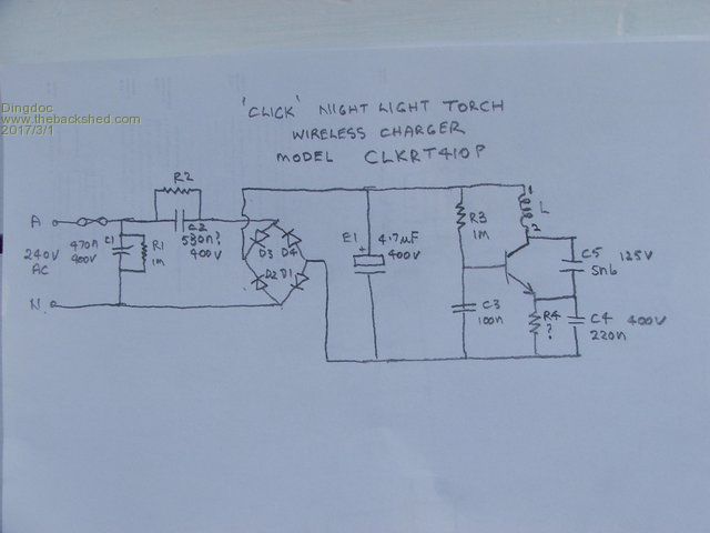 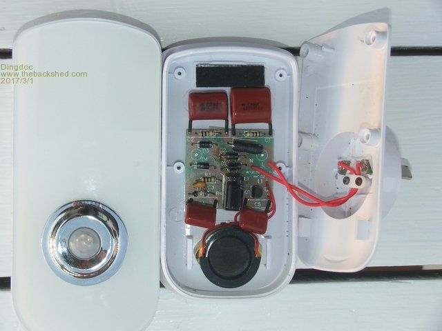 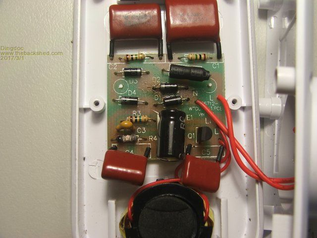 |
||||
| Dingdoc Regular Member Joined: 23/09/2009 Location: AustraliaPosts: 76 |
Forgot to give the transistor specs in the last post - It's an MJE13001 400V (CEO) 750mW 200mA. It looks like the whole circuit runs at a quite high voltage! The inductor has a ferrite ring 'side-on' in the coil former to improve magnetic coupling with a similar 'secondary' coil in the torch. Note that the cover is held on by 4 screws under plugs and hooks either side of the coil. |
||||
| Dingdoc Regular Member Joined: 23/09/2009 Location: AustraliaPosts: 76 |
Success at last! After nearly 12 months wait I finally managed to get details of the cooked resistor. Friends in the city happened to have 2 of these , one of which had 'died' just like the one I already had, and they sent me a good clear photo of the internals as well as the dead unit! 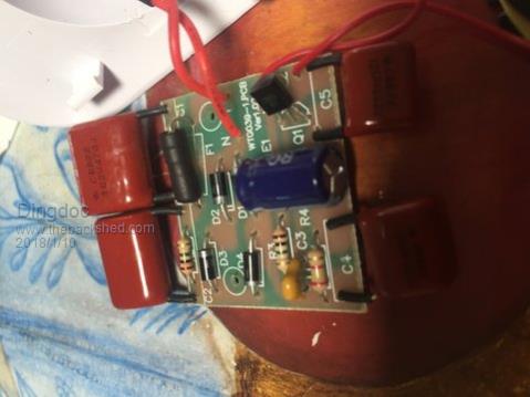 So, the cooked resistor would appear to be 2k4! This was easily replaced but a check of the electro and transistor revealed they were not too healthy so I ordered some replacements online. When the parts arrived and were fitted it was dis-appointing to find the charger would still not work, but a check of the transistor with the component tester revealed that its pins were BEC instead of ECB like the original! Once it was reversed everything worked as it should and I quickly had the second one working too. As a coincidence, the Aldi catalogue arrived in the letterbox the next day and I was surprised to see these same units on sale! |
||||
| Peekay Newbie Joined: 08/04/2018 Location: AustraliaPosts: 1 |
G'day Dingdoc, The same model/unit as yours died in my workshop. The 2.4K resistor had smoked itself to death cooking the adjacent capacitor as well. (It was turned inside out). Put a 5w resistor in with a new chunky capacitor from Jaycar This lot started overheating as well. Maybe the transistor was turned on all the time? Put a new 13001 in and like you. Nothing! Found your post -thanks and turned the transistor around. Functioning well if not a bit physically oversize!!. The original tranny is not as per specifications. The pcb even has a transistor profile on it and they'd fitted opposite to the profile to suit themselves at manufacture. It's a first for me Hopefully if the same failure happens again the 5W resistor will survive and blow the fuse Cheers |
||||
| Guzzi Newbie Joined: 30/09/2020 Location: New ZealandPosts: 1 |
Many thanks Dingdoc, This is exactly what I was looking for. I have one of the same chargers with the same burnt out resistor. I traced the circuit and used a circuit simulator to try different resistor values but the results were inconclusive, partly because I was just guessing the effective inductance of the coil (particularly when the torch is in place). You have saved me some head scratching and experimentation. Cheers for your post mate! |
||||
| CIL-E01 Newbie Joined: 10/02/2021 Location: United KingdomPosts: 1 |
Thanks to this thread, I can now fix one of these devices which just came in for repair. Much appreciated for the circuit and component values. :) |
||||
disco4now Guru Joined: 18/12/2014 Location: AustraliaPosts: 1130 |
Just some keywords to help someone find it in the future. CLICK NIGHT LIGHT TORCH WIRELESS CHARGER CLKRT410P F4 H7FotSF4xGT |
||||
| Old Andy Crepit Newbie Joined: 11/10/2023 Location: United KingdomPosts: 1 |
This probably way too late but having had one of these passed to me by a neighbour I went through much of which has been written here but believe some of the advice given does have problems. I needed the value of the burnt resistor which I found on another site but the damned thing still didn't work so I took another link to get here. I did replace the resistor with a much higher rated one which got too hot to touch so I replaced the transistor which also got hot. So I then did what I should have done as a matter of course and checked the reservoir electolitic, the biggest cause of countless problems which have caused expensive gear to be dumped in frustration and it was of course open circuit. So .... Replace all three components. The transistor may have survvived because the resistor failed first. DO NOT USE over rated resistor because it may cause a FIRE before failing. The replacement transistor will probably need to be reversed so identify the base first. It might be an idea to put 2 capacitors in parallel to improve reliability as 8uF will not affect operation. |
||||
| The Back Shed's forum code is written, and hosted, in Australia. | © JAQ Software 2026 |
