
|
|
Forum Index : Electronics : Inductance Saturation Tester Build
| Author | Message | ||||
| Solar Mike Guru Joined: 08/02/2015 Location: New ZealandPosts: 1215 |
As I cannot progress my big inverter until the choke saturation issue is sorted out and prompted by Warps excellent notes on a better way to build an inductance tester, Link, have decided to do yet another project and build a decent saturation tester. The following circuit was breadboarded in sections and now I have drawn the full circuit in DipTrace prior to making a PCB. The PCB will bolt directly to the huge 1.5kg 160,000uf low esr cap terminals, with sockets for the plug pack 12 volt supply and main variable supply. The CD4046B phase lock loop chip makes an excellent VCO with 1:1 mark space ratio and a range from 0 to the megahertz region, determind by Cx thus the unusual choice there. Rest is pretty familiar, using IR2110 driver and mosfets, dual rectifiers I had on hand and small 1 watt sip 12:12 volt isolated supply for H0 power, have limited the mosfet drive currents to 1.2 amps by 10R resistors as I couldnt find any 10uf low esr caps with ripple currents higher than 1.7amps, RS 714-9622 Nichicon Aluminium Polymer Capacitor 10μF 25 V dc will work here. Point note with the big inverter driving 6 parallel fets and 12 amp driver will require few of these caps in parallel to be reliable, dont use a hunlow brand off EBay they most likely will fail. The inductor to test will bolt to the pcb via big screw terminals, current probe to the scope will be in an external jiffy box powered by 9v battery, unless I slurge out on a DC clipon current probe adapter for the scope. Current Probe So please cast your eyes over this, any stuffups let me know prior to making the pcb, will post that here when done. 2017-05-25_110229_Saturation_Tester_Circuit.pdf Cheers Mike |
||||
| Tinker Guru Joined: 07/11/2007 Location: AustraliaPosts: 1904 |
Wow Mike, that looks impressive. I do hope the results are equally impressive. I made PCB's for a much more basic version but am still waiting for the high current schottky rectifiers before testing commences. Mine will initially use 2 parallel 33,000uf/40V screw terminal capacitors which have a combined ripple current of 46Amps. If that proves not good enough I can always connect my super caps (12 x 3000F) but that would limit the voltage to 2.7x12. I also epoxied together two two of the big choke cores (out of Aerosharp 3KW) for my test choke. They have big airgaps, 2 x 1.6mm per core, and an odd magnetic material. It looks like very thin laminations but its not, when I abraded the surface prior to epoxying, it came off in very thin flakes. So I guess its some sintered material. Looking forward to see how this non saturating choke idea turns out. Klaus |
||||
| Warpspeed Guru Joined: 09/08/2007 Location: AustraliaPosts: 4406 |
Excellent work guys, you won't be disappointed. Mike, I really like your circuit, its all there, and should work very well. I never thought to use a 4046 VCO, that is a brilliant suggestion, a single turn logarithmic pot to stretch out the low frequency end might be worth a try. The low frequency end probably need not go below 20Hz, as screen flicker with an analog CRO can be annoying. Probably not much reason to go much above about 10 Khz either, as if it is a very small inductor, the dc voltage can be reduced to slow down the rate of current rise. That Hall current probe with the opening jaws looks like a real beauty ! One last thought about the electrolytic. If anyone plans to use a low cost aluminum electrolytic, if its really suffering, it will tell you by getting unreasonably hot long before it explodes. Or put another way, if its not getting outrageously hot, its working fine ! Cheers, ĀTony. |
||||
| Solar Mike Guru Joined: 08/02/2015 Location: New ZealandPosts: 1215 |
PCB Design completed, yet to do final checks prior to etching. Bolts on top of main capacitor screw terminals. Heatsink will be 2 small pieces of flat alloy bolted with insulation media to fets and dual diodes. 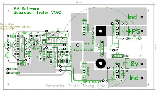 |
||||
| Warpspeed Guru Joined: 09/08/2007 Location: AustraliaPosts: 4406 |
Looking good ! Cheers, ĀTony. |
||||
| Solar Mike Guru Joined: 08/02/2015 Location: New ZealandPosts: 1215 |
Have been using the device testing out various coils, for currents up to 30 amps, no heatsink is required on power devices, however the 12 volt isolation supply chip is extremely noisy and generates considerable levels of RF hash right up to 1 MHZ or so, this capacitively couples to everything making low current measurents difficuilt. Fixed by adding small ferrite beads with 3 turns to all active pins, this brings the noise hash down sufficiently to enable measurements of <1 amp in the test coil. Maybe just the brand of the 1212S, but if I was going to use these again would mount it inside a metal cage with feedthru caps for wire connections. The power diodes work great when the fets turn off and shunt power in the test coil back into the main supply cap, 30 amps coil = 3 amps drawn from the supply as a rough estimate 10:1 I found easist way to measure coil current was to place a precision series resistance in the coil circuit, used a small piece of pcb with additional 0.25mm thick copper foil soldered to the copper side and a 0.01 ohm 3 watt 1% smd resistor, the thick foil is very low resistance and allows any heat generated in the resistor be conducted away. 1 amp = 10mV on the scope. Will post some more photo's tomorrow. Cheers Mike 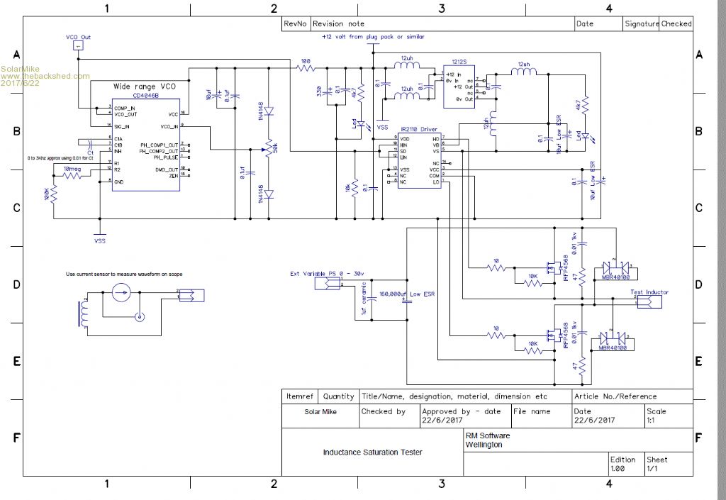 |
||||
| Warpspeed Guru Joined: 09/08/2007 Location: AustraliaPosts: 4406 |
Great stuff ! The dc voltage you test at does not really matter that much, but at very low dc voltages the voltage drop across the diodes becomes a larger percentage, and the total energy stored in the main reservoir electrolytic is proportional to voltage squared. So the hot tip for lowest energy loss, if you are testing a monster choke to very high peak currents, its probably better to do it with a fairly high applied dc voltage and a shorter "on" time than the other way around. I use a 30v 3 amp supply and can test up to 80 amps peak very easily, and have never run out of dc input power to do it. Anyhow, great results there Mike. Cheers, ĀTony. |
||||
| Tinker Guru Joined: 07/11/2007 Location: AustraliaPosts: 1904 |
Hi Tony, My choke tester is almost ready, wound the test coil today and now am waiting for the epoxy to seal it solid. Regarding your comments above, what frequency would you set the the 4046 on for high current testing? Its range is 50Hz to ~3KHz as per copied schematic from Solar Mike. The hall current sensor I got does up to 50A, the test coil has 125 turns and uses 2 choke cores (ex Aerosharp big choke). I can also experiment with different air gaps, I assume smaller gap = earlier saturation? The original air gap was 2 x 1.6mm which is quite big. Klaus |
||||
| Solar Mike Guru Joined: 08/02/2015 Location: New ZealandPosts: 1215 |
Hi Klaus, I changed that timing c to 3300pf to extend the high frequency to approx 5.6 KHZ, start with the highest frequency and a nominal 12 volts or so, then wind down the frequency until noticeable current is being drawn so you can set your scope up etc, then play with voltage and frequency. Cheers Mike |
||||
| Warpspeed Guru Joined: 09/08/2007 Location: AustraliaPosts: 4406 |
Yes, that is the way to do it. Start off at max frequency and a low nominal dc voltage until you see some low amplitude ripple current on the oscilloscope. Then gradually alternately reduce the frequency and increase the voltage so the triangle wave you see gets taller and wider. The rule of thumb method of choke construction is to first determine the wire size that will just carry the required maximum continuous current without seriously overheating. Then put on as many turns that will possibly fit onto the core. You then get to play with the air gap. There is a direct trade-off between inductance and dc saturation level. Just remember that the peak current your inverter choke sees will be 1.414 times the rms inverter load current times the transformer ratio, plus a generous safety margin. Cheers, ĀTony. |
||||
| Solar Mike Guru Joined: 08/02/2015 Location: New ZealandPosts: 1215 |
Finally taken a few pics. Tester mounted on 160,000uf cap, note the 12-12v isolated supply for upper mosfet is mounted on external board with ferrite beads to remove HF hash. Current sample point is 0.01 1% SMD 3W resistor with additional copper foil soldered to scrap of PCB, solid brass terminals used for connection to test inductor. This test choke is from an old oil cooled filament transformer that supplied mercury vapour rectifiers in a 100KW AM transmitter, re-arranged as a choke with a 2mm gap, actually works quite well 2400 amps/T and 1.48uh/Tsq, so 6 turns would be good for 400 amps so will easilly do the 10kw inverter, but the waveform is not as linear as Ferrite or C core and may have higher eddy losses. 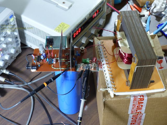 Waveform: Yellow is 5 amps/div, saturation just starts @30A, blue is mosfet drive, note not that linear. 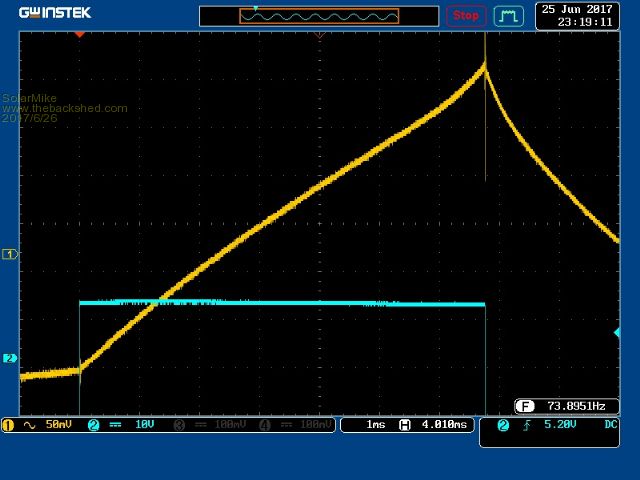 Here is a C core with 1.5mm gap core is 38mm H x 36mm W x 60mm inside hole, saturation is 1920 A/T with 1.05 uH Tsq, so 7 turns would be required @274 amps. Don't think its big enough and the hole is a bit small to fit the wire size, would be ok if I had two and put one on each leg of the main transformer, not sure where I can get a second one, EBay perhaps. 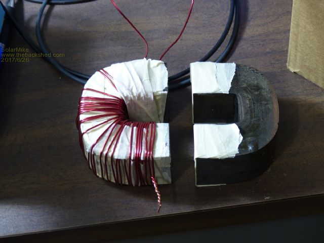 Spikes in the waveform caused by me swapping power supply to a cheap switch mode variable PSU, puts out some hash. Yellow trace 10amps/div to onset of saturation. 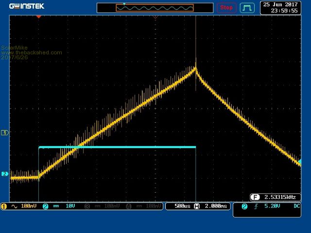 Here is the typical 65 ferrite E core, with 0.5mm gap, 20 turns saturation @18amps, I feel this won't work that well at the required 300 amps peak. 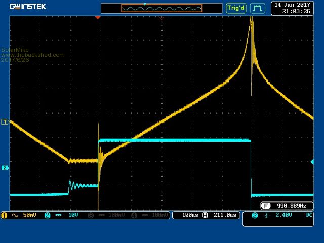 I have a bunch of large 100mm ferrite rings, tried one and it performed similar to the E core above, go out the dremmel and cut increasingly larger chunks out of it to see how it would perform with differing air gaps, after 8mm or so, bigger gaps have less affect, best magnetic saturation I could get was 400 A/T with about 10 turns required, so it would max out at 40 amps, not high enough, I have 10 of these cores but wasnt prepared to chop them all up and stack together, a more distributed ring core like powdered iron would be better, but they are expensive in that size. The C core seems the best core to use, its fine laminations give good magnetic linearity. However a choke made from a quality large transformer with grain oriented steel maybe ok.... Has anyone tried this?. Cheers Mike |
||||
| Warpspeed Guru Joined: 09/08/2007 Location: AustraliaPosts: 4406 |
Probably the best thing for us to use would be the tape wound C cores you show in the third picture. These grain oriented silicon steel cores are wound from 0.3mm steel strip onto a rectangular mandrel, then cut in half and the edges precision ground. This is exactly the same material that our large toroids are made from. The advantages are that the grain oriented silicon has the highest magnetic saturation level of any available material, and the steel strip is thin reducing eddy current loss to a practical minimum. It also has a very high permeability when ungapped, which gives high inductance per turn for our toroid reducing magnetizing current, and hence no load inverter idling current. Its really good stuff ! The only company making these strip wound cores in Australia are "AEM Cores Ltd" in South Australia. They come in sizes from tiny up to a 290Kg monster with a 600mm x 130mm window. And AEM can also optionally supply fiberglass bobbins for winding the coil onto. I have no idea what these things cost new, but what we require should not be overly large. I can not give any precise guidance for required size, but energy storage goes up with both the mass (weight) of the steel core and width of the the gap. A rough as guts guess might be about 1Kg of steel core per inverter Kw. The Inspire and Aerosharp chokes weigh about 2Kg. We might be able to nail this down a bit further if a few of us test some cores. I hope to begin a new thread on "inverter magnetics" but need to gather a bit more information before I start that. I think there is a very great deal to be gained here by a more methodical approach to the whole choke/transformer/output filtering problem. There is nothing that I can find in the literature about this topic, its all "propriety" information. And the professionals that design inverters are not about to give away secrets that will help opposition companies to compete. So we do what they do. Reverse engineer other successful commercial products, work backwards and try to figure out what they did, but more importantly try to learn the reasoning and methodology behind the engineering. Cheers, ĀTony. |
||||
| Solar Mike Guru Joined: 08/02/2015 Location: New ZealandPosts: 1215 |
One seller on EBay is selling these bare Hitachi C Cores Hitachi C Core they come as two C core pairs and a single bobbin; he has other types also of smaller sizes. I have obtained one and done some tests: 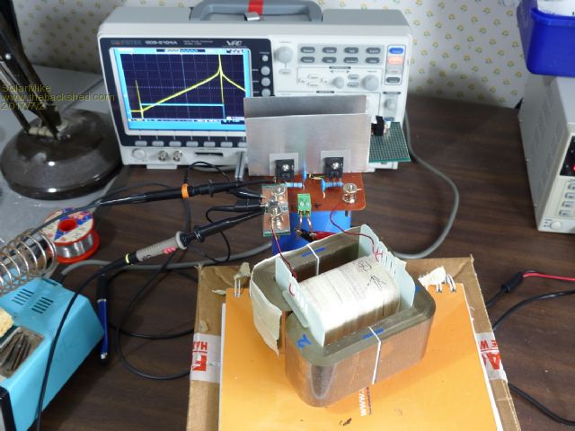 Size of each C core is 55mm height, 15mm width, 20 x 76mm inside gap, they have very thin metal strip that is razor sharp and yes bits do flake off, so carefull handling is called for. Using 1mm spacers (total 2mm gap) and a test winding of 50 turns of 1.2mm dia wire. Saturation = 40 amps or 2000 A/Turn With Voltage = 40 volts and duration = 0.0032 seconds Inductance = 3200 uH or 1.28 uH/T^2 So 6 turns = 46uH and 333 Amps peak, I require 200 amps with 280 amps peak, so this core should work nicely. For a smaller inverter only 1/2 the core would be required, I tried increasing the air gap to 2.6mm, saturation increased somewhat but then more turns required, so there is a practical limit. I was thinking of splitting the core into 2 separated inductors of approx 25 uH each to allow the cable size to fit better, one in each leg of the transformer, so halfing the core means the AL is now 0.64 uH/T^2 and 6 turns required in each. Guess if I split the inductances into 2 using the same combined dual core then only 3 turns would be required for each winding cutting down the wire resitance. Here is the tester display, yellow 10amps/div: 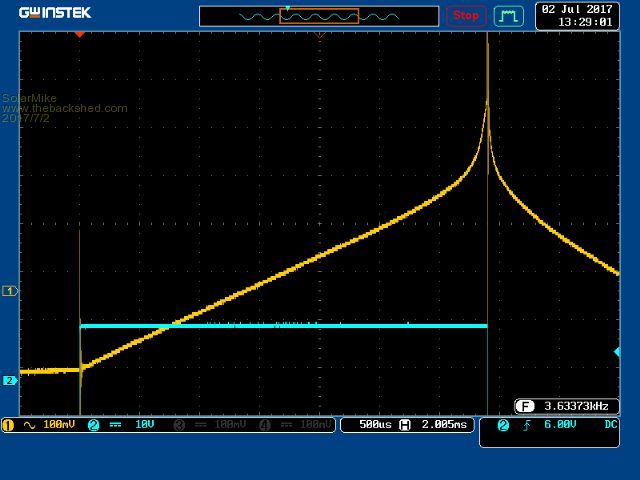 These cores are a bit expensive, but cannot locate anyone in NZ making them, will contact "AEM Cores Ltd" in South Australia and see what their prices are. Cheers Mike |
||||
| Warpspeed Guru Joined: 09/08/2007 Location: AustraliaPosts: 4406 |
Not surprised nobody in NZ makes these, we have only one manufacturer in oZ. For pricing, the closest size I could find in the AEM catalogue is 8.6cm squared compared to your 8.25 cm squared. That is for a single core pair, you have two pairs there + bobbin.  Cheers, ĀTony. |
||||
| The Back Shed's forum code is written, and hosted, in Australia. | © JAQ Software 2026 |
