
|
|
Forum Index : Microcontroller and PC projects : My God, there are a lot of them....
| Page 1 of 2 |
|||||
| Author | Message | ||||
Grogster Admin Group Joined: 31/12/2012 Location: New ZealandPosts: 9932 |
I am now totally lost with my attempts to play with MOSFET's.  I went searching for a suitable one the other day at element14, and there are more then 8,000 different discrete single's. I am not having much luck finding what I need, even when I use the filters. What I need is: - P-channel MOSFET (as a high-side switch with 'Helper' NPN transistor arrangement) - SOT-23 package - Vsd of 20v or so(more is OK) - Vgs of 15v or so(more is OK) - sd current capability of 3A or so. I am not able to find anything to suit these requirements using the element14 filters - perhaps someone here who knows their part numbers, can recommend something? The main issue is the Vgs figure. Most of the P-channel MOSFET's I find have a low Vgs, and when I need to pull the gate high to 12v or so, this is not being satisfied. The next issue is that any devices I find that CAN have a Vgs of 12v or more, can only carry 100mA or so in the sd path, so that makes them unsuitable too. Can anyone save my sanity and suggest a couple of part numbers that might suit me?  Smoke makes things work. When the smoke gets out, it stops! |
||||
| panky Guru Joined: 02/10/2012 Location: AustraliaPosts: 1120 |
G, My understanding is that Vgs and Vgs(th) are two different things. Vgs is the absolute maximum gate source differential without destroying the device, Vgs(th) is the gate source threshhold voltage where the MOSFET starts to turn on. The following might be close to what you need from RS Components. PMV65XPEAR Cheers, panky ... almost all of the Maximites, the MicromMites, the MM Extremes, the ArmMites, the PicoMite and loving it! |
||||
| Grogster Admin Group Joined: 31/12/2012 Location: New ZealandPosts: 9932 |
Yes, that is my understanding too. When used as a high-side switch though, the gate is pulled up to the supply voltage via 100k or so - 12v in this case - so I am not so worried about the Vgs(th), moreover the Vgs figure. The device you link to is also available at element14, so I can get them there if I want. The maximum Vgs for this device is 12v though, so that leaves no safety area at all, which is why I was looking for a Vgs somewhere in the area of 15v, cos then I could use with 12v circuits and also 13.8v circuits. Thanks for posting though, as the device you linked to is the frontrunner so far. Smoke makes things work. When the smoke gets out, it stops! |
||||
| panky Guru Joined: 02/10/2012 Location: AustraliaPosts: 1120 |
G, This circuit might be the workaround - a few more components but would let you use the MOSFET above. 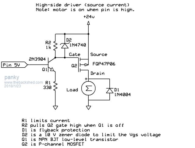 panky ... almost all of the Maximites, the MicromMites, the MM Extremes, the ArmMites, the PicoMite and loving it! |
||||
crez Senior Member Joined: 24/10/2012 Location: AustraliaPosts: 152 |
Using the above circuit, after deleting the zener, Vgs will be very close to (Vb-.6)* R2/R1 For example if you want 10v gate to source and you have 3.3v input, then R2/R1 will be 10/(3.3-0.6)=3.7 .This would be satisfied by R2=1k2 and R1=330R. This relationship is mostly independent of the supply voltage. I wouldn't use this for high speed pwm, but it would be fine for 1kHz or less. If it is keeping you awake at night, add the zener anyway.  |
||||
| MicroBlocks Guru Joined: 12/05/2012 Location: ThailandPosts: 2209 |
The should be mosfets that are capable of using simple digital signal to switch on and off. I know they exist, but do not have any part numbers unfortunately. Microblocks. Build with logic. |
||||
| robert.rozee Guru Joined: 31/12/2012 Location: New ZealandPosts: 2499 |
any small mosfet is likely to have a low Vgs(max). a very standard approach i saw used when working in R&D was an 8v zener diode across a relatively high pullup resistor (150k or more) and an 8k2 or thereabouts resistor down to the collector of the NPN transistor. assuming you're not after a super-fast switching time, the pullup can be quite a high value, as it merely serves to drain away any charge held on the gate. as i recall the gate capacitance of a MOSFET is typically down in the tens of picofarads range. generally Vgs(max) is never very high at the best of times - i don't recall seeing MOSFETS where it was much more than 25 volts or so. even on 12v systems, including some sort of protection in the form of a zener is considered prudent. cheers, rob :-) |
||||
| CaptainBoing Guru Joined: 07/09/2016 Location: United KingdomPosts: 2171 |
Hi Grogs. Is switching high-side a necessity? If you are "just" PWMing that motor, maybe something like FQP30N06L and switch the lowside with a micromite pin direct to the gate (2.5v VGSThresh). I would put a 100K pulldown to GND from the gate just to cover your backside in the twinkle that it takes to configure the pin as an output. Used this myself for motors and solenoids with no issues. |
||||
| PicFan Senior Member Joined: 18/03/2014 Location: AustriaPosts: 133 |
IRLML-2244(SOT-23) IRFR-4620(SOT-23) IRF-830 (DPAK) Maybe it helps ? |
||||
| CaptainBoing Guru Joined: 07/09/2016 Location: United KingdomPosts: 2171 |
dammit - SOT  |
||||
| Grogster Admin Group Joined: 31/12/2012 Location: New ZealandPosts: 9932 |
Just to clarify for folks here, the example diagram that panky posted is NOT what I am doing. I am trying to find a MOSFET to act as a high-side switch(with helper transistor) for the battery charging switch thing I discussed in another thread. This is where I want to be able to turn OFF the battery charging under MM control, once a certain time or battery voltage has been achieved, to prevent overcharging. Although, with a trickle-charging arrangement, I might just be making things overly complex for myself for no good reason....  That's the idea, anyway. HAS to be SOT-23, as I have very little PCB real-estate to shoe-horn the extra parts into. Anything bigger - even TO-92 - will be too big. Switching is simply 100% on or off via an I/O pin. No PWM. ON for up to 24 hours, then OFF till the plug-pack-charger is removed. I am interested in the zener idea. I have a ton of DMP2305 MOSFET's, but they have a maximum Vgs of 8v. Vgs(th) of 0.9v max. Vdss of 20v. Id of 4.2A MAX. These are my current favourite for all 3v3 and 5v circuits, but I was thinking they were totally out cos of the 8v Vgs, when I want to put 12v on the gate. With the zener idea, I am now thinking I could use a zener on this MOSFET(5v or 6v or so) and then use THAT one - along the lines of what panky and robert.rozee suggest. Thoughts? Smoke makes things work. When the smoke gets out, it stops! |
||||
| Grogster Admin Group Joined: 31/12/2012 Location: New ZealandPosts: 9932 |
@ Rob: Is this the kind of idea you are talking about.... 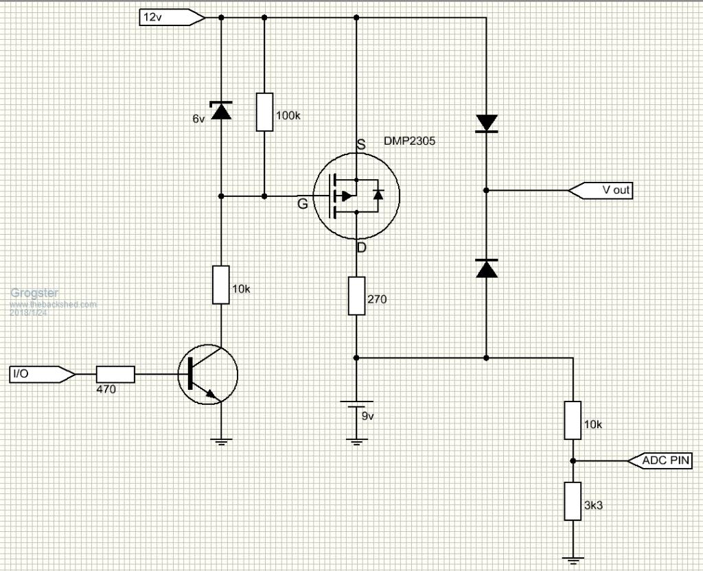 Smoke makes things work. When the smoke gets out, it stops! |
||||
| robert.rozee Guru Joined: 31/12/2012 Location: New ZealandPosts: 2499 |
grogster: that is exactly what i'm talking about. looking at panky's circuit, i think it may also work. Q1/R1 form a constant-current sink, drawing (3.3-0.6)/330 = 8mA when 3.3v is applied to the base of Q1. when the base of Q1 is low (less than 0.6v), no current flows. the only disadvantage of this arrangement is that IF the base of Q1 is held high while there is no collector load for Q1 (ie, R2 and D2 missing), then the 8mA gets drawn from the micromite's control pin and flows down through Q1's BE junction. R1 and R2 could probably be scaled up by a factor of 10 (ie, R1=3k3, R2=10k) to reduce the current to 800uA. note that below a few milliamps, zeners may not regulate particularly well, but in these sorts of applications that doesn't really matter. cheers, rob :-) |
||||
| Grogster Admin Group Joined: 31/12/2012 Location: New ZealandPosts: 9932 |
Awesome. Thanks a bunch. That means I can use one of the 2305's I have here, as I have several hundred of them in SOT-23. I'm not entirely sure why I did not think of using a zener on the gate myself, but my little grey cells sometimes......Smoke makes things work. When the smoke gets out, it stops! |
||||
| CaptainBoing Guru Joined: 07/09/2016 Location: United KingdomPosts: 2171 |
That FET is a nice little beastie. How about you increase the zener to 8V2 (or as much as 11V) then you can get rid of the transistor and it's 470R, connect the bottom end of the 10K direct to a 5V tolerant pin set to OC. Rob is spot-on with his warning bout Iz - you might want to drop that 10K to 3K9 or even 3K3 just to make sure the zener does its job properly. chopped two components from your estate! Ignore this if your 12V is "nominal" - unregulated walwarts have a tendency to be very "about" (read as 17V off load - that would nuke the PIC pretty quickly) |
||||
| Grogster Admin Group Joined: 31/12/2012 Location: New ZealandPosts: 9932 |
2305's maximum Vgss is 8v. Would not an 11v zener kill it? Where are you getting your 11v reference point with respect to the 2305 MOSFET? Just curious. Smoke makes things work. When the smoke gets out, it stops! |
||||
| CaptainBoing Guru Joined: 07/09/2016 Location: United KingdomPosts: 2171 |
If the breakdown of the Zener is 11V anything over that "bleeds" backwards through the zener - in this case a single volt. This is enough to turn the FET on (although a bit close to 0.9V). That 1V at a mA or two is easy sucked away through the OC pin on the uC. With the pin "hi", there is no path to ground so both sides of the zener (and the gate of the FET) are pulled to the supply - Vgs is now zero and the FET is off, take the pin low, source is still 12V, gate is now 1V (Vgs is -1V) and the FET turns on. Am I missing something? Worried now. hate hi-side stuff it is all backwardsEDIT: eeek "-1v" should be -11V - you are right the FET is dead at this point - ignore me! unless you have a 12v tolerant pin on your PIC you will need that tranny |
||||
redrok Senior Member Joined: 15/09/2014 Location: United StatesPosts: 209 |
Hi Grogster;I kike panky's current sink circuit with some changes: 1. Use a 3.3V pin. 2. Change R1 to 680 ohm. 3. Ditch the zener as its not required. The current through the 680 is: (3.3V - .6V) / 680 = about 4mA 4mA * 1K = about 4V guaranteed to fully turn on the MOSFET. and The 1K gate resistor will turn off the MOSFET fairly rapidly. BTW, bipolar transistors are perfect for current sinks. redrok |
||||
palcal Guru Joined: 12/10/2011 Location: AustraliaPosts: 2039 |
@ grogster Would the circuit of the back light control on the MM Backpack, using two Mosfets be of any help. Paul. "It is better to be ignorant and ask a stupid question than to be plain Stupid and not ask at all" |
||||
| redrok Senior Member Joined: 15/09/2014 Location: United StatesPosts: 209 |
Hi palcal;Can you elaborate a bit, I don't understand. redrok |
||||
| Page 1 of 2 |
|||||
| The Back Shed's forum code is written, and hosted, in Australia. | © JAQ Software 2026 |
