
|
|
Forum Index : Microcontroller and PC projects : The PIC32MZ board from OLIMEX
| Page 1 of 2 |
|||||
| Author | Message | ||||
| Micro-80 Newbie Joined: 03/03/2017 Location: Russian FederationPosts: 26 |
The new version of the board PIC32-HMZ144 is now available with a microcontroller PIC32MZ2048EFG144. 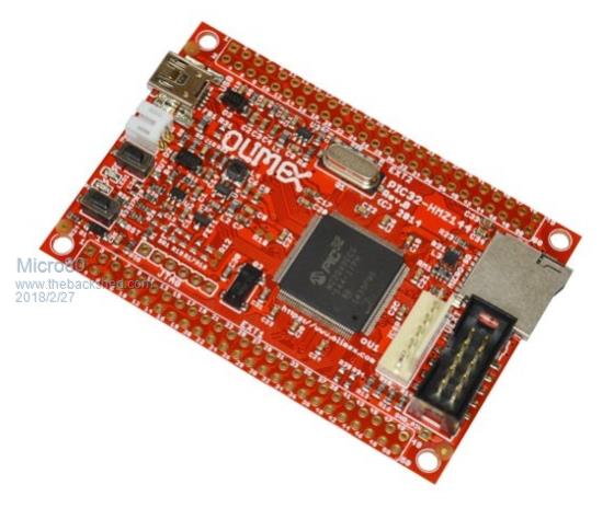 |
||||
| JohnS Guru Joined: 18/11/2011 Location: United KingdomPosts: 4298 |
That looks suitable for the MMX MMBasic. Have I understood correctly? John |
||||
| matherp Guru Joined: 11/12/2012 Location: United KingdomPosts: 11144 |
The SDcard won't work as wired |
||||
| JohnS Guru Joined: 18/11/2011 Location: United KingdomPosts: 4298 |
Thanks, Peter. John |
||||
| matherp Guru Joined: 11/12/2012 Location: United KingdomPosts: 11144 |
Also the MMBasic I2C is compromised by the way the SDcard is wired and the only thing on the Olimex UEXT port that works is MMX I2C2 on the pins they specify for I2C. This is the one problem with the Peripheral select mechanism on the PIC MX and MZ chips. It gives flexibility but also means that PCBs developed by different organisations are likely to be incompatible to a greater or lesser degree. |
||||
| MicroBlocks Guru Joined: 12/05/2012 Location: ThailandPosts: 2209 |
Would it not be possible to make those pin assignments configurable in mmbasic? Maybe with OPTION and only available after a restart. Then every board can be supported. Microblocks. Build with logic. |
||||
| JohnS Guru Joined: 18/11/2011 Location: United KingdomPosts: 4298 |
There's only one matherp :) But I expect anyone can ask for the source, and make the changes (if they're possible i.e. if the board can be made to do what is wanted). Then it would help to offer the result back to Peter (if he will take it?) and/or Geoff. John |
||||
| matherp Guru Joined: 11/12/2012 Location: United KingdomPosts: 11144 |
I've thought about that but it is very difficult. For a start the flexibility is limited. There is a complicated set of tables in the datasheet that say what pins can do what and it is easy to run out of any available pins for a specific use. Also, some pins are not flexible at all (All I2C pins and all SPI CLK Pins) So if we take the Olimex board as an example, they have completely compromised I2C channel 1 by using its clock pin for SPI. The whole philosophy of the Microchip development environment (Harmony) is that pin allocation is done before coding starts and is then fixed. MMBasic already complicates this by only allocating "extended" functions like I2C, SPI, UART, Count when they are used and allowing the user to de-allocate them. I know Geoff has considered removing this flexibility on the higher pin-count chips where it isn't so important. Basically, then if you allowed the user to choose allocations they could only do so with the PIC datasheet in front of them and they would find it easy to completely b....r things up. This would be a nightmare to support and document |
||||
| JohnS Guru Joined: 18/11/2011 Location: United KingdomPosts: 4298 |
It's most odd that Olimex managed to foul things up so badly. John |
||||
| matherp Guru Joined: 11/12/2012 Location: United KingdomPosts: 11144 |
They haven't really - they have just chosen a different allocation. There are 6 I2C channels on the MZ each with fixed pinouts. I happen to use 1 and 2 and Olimex have compromised 1. The problem with flexibility is that there are lots of ways of doing the same thing but it isn't possible in code to easily change between them. For example each I2C channel uses 3 Interrupt addresses which are hard coded to that channel and of course the control register addresses are also fixed by channel. It would be completely impracticable for me to code I2C in a way that allowed flexibility but had I started using channels 4 and 5 on day one then there wouldn't have been an issue with that particular conflict. |
||||
| JohnS Guru Joined: 18/11/2011 Location: United KingdomPosts: 4298 |
Oh well, one of those things then. Might have meant an affordable ready-made board for people who don't fancy the soldering but I suppose they can just use the RPi and side-step all such issues! It's Sod's Law that both this Olimex board and the PIC32-EMZ64 Olimex board are unsuitable. John |
||||
| robert.rozee Guru Joined: 31/12/2012 Location: New ZealandPosts: 2499 |
perhaps what one wants for the MZ may well be: - a minimal board with just the processor, Vcap, crystal and 3v3 regulator/caps on board (ie, no sockets or LEDs). - 0.1" header for SD that matches up with the pinout of the cheap SD socket boards available on ebay, in a location where the ebay board can just hang out the side - 0.1" header for power, ICSP and serial console combined. - a 0.1" header for VGA output. - all 100 of the pins brought out to four 2x13 headers arranged around the processor. - strictly fits within a 100mm x 50mm footprint. very similar to the snadpic boards that folks were using early on, and that can be sold with just the MZ processor populated. also, that can be posted around the world in a standard envelope. if limited to 100mm x 50mm, the PCBs can be fabricated in 4 layers for around us$2.50 each. cheers, rob :-) |
||||
| MicroBlocks Guru Joined: 12/05/2012 Location: ThailandPosts: 2209 |
I have done something similar in 2013 with a qfp-100 chip (MX795) for a customers project. The absolute minimum can be done on a 37x37mm board, double sided. with components on both sides. All 100 pins is not really necessary as a lot of pins are VCC and GND. Also the OSC pins would not need to be available. 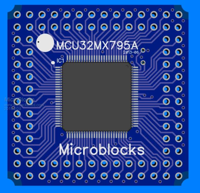 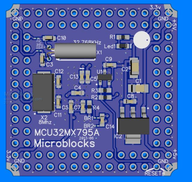 This included a 32Khz crystal for the onboard rtc, a supervisory circuit and a 3.3v power supply. Bump the board size to 50x50mm and you would have some room for specific pins, but this will probably need a 4 layer as the pins would be in the way. You can even add a 1455 to this to make it even easier to use. Microblocks. Build with logic. |
||||
| isochronic Guru Joined: 21/01/2012 Location: AustraliaPosts: 689 |
maybe I should rework this a bit : sn-7x I have been considering it, mainly putting a rtc (spi) on it and feeding the 32khz to the MZ and nudging the seral io to be more compatible. Fun, but ... there was not much interest. |
||||
| JohnS Guru Joined: 18/11/2011 Location: United KingdomPosts: 4298 |
It would be a way to get a prebuilt board so I imagine would be interesting - but price may be a major problem. Olimex make an entire board (PIC32-HMZ144) for 21.95e (US $27, �19). Reinventing the wheel is looking costly. John |
||||
| MicroBlocks Guru Joined: 12/05/2012 Location: ThailandPosts: 2209 |
Boards that are already available can most of the time not be beaten by price. If we were to make another specific one then it would only sell a few and that would not be enough to even recoup the costs. This remains solidly in the hobby/have too much time domain. :) My suggestion to adapt the software, maybe only as a compiler switch, to adapt for certain easily available boards is better. It would be a bunch of defines that have to be worked out but ones that is done a specific version for a board is just a compile away. Microblocks. Build with logic. |
||||
| robert.rozee Guru Joined: 31/12/2012 Location: New ZealandPosts: 2499 |
all far too complicated. concentrate on the absolute mimimal requirements: 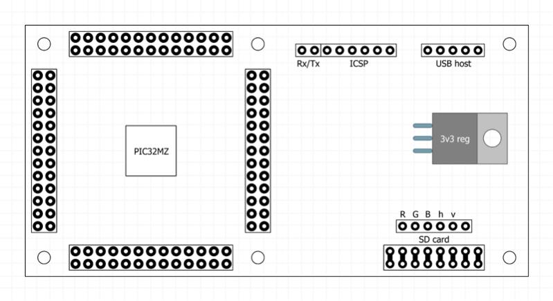 the MZ processor and 3v3 regulators will be the only active components. passives will be filter caps, resistors for the VGA mixing/levels, and a pullup on the reset line. plus the 24MHz (?) clock crystal. the SD 8x2 header leverages off the adapters available on ebay. NO onboard 1455, NO onboard connectors beyond footprints for 0.1" pin headers. this is a board that can be shipped with just the MZ processor fitted for minimal cost, and the end user can then add whatever they want. cheers, rob :-) |
||||
| MicroBlocks Guru Joined: 12/05/2012 Location: ThailandPosts: 2209 |
You are almost there. Just draw some traces and it is ready. Don't wait for someone else. Microblocks. Build with logic. |
||||
| WhiteWizzard Guru Joined: 05/04/2013 Location: United KingdomPosts: 2962 |
Each persons 'perception' of minimum requirements will vary. Take one of the many TQFP (or LQFP) Breakout Boards and use that as the 'minimum'. Some versions specific for the PIC32 will have provision for the decouplers and ICSP. However, ICSP is redundant if you have a MicroBridge module. And if you do have a MicroBridge, then no need for any vReg. Add one of Grogsters SD Card modules (that he did for the E100) and you have SD functionality. Add three 120R resistors along with three 1N4148s and you have VGA functionality. To save a VGA connector, simply cut and solder on a 'spare' VGA lead that you may have lying around. By the way, the is how I built my test MMX144 module whilst Peter was working on the code (apart from I used a BoB with onboard vReg since the MicroBridge module wasn't available at that time). And by the time you add a beeper, TFT 40-way, and general I/O connectors, then you have the MMX144 module - PCB already designed! So really depends what people perceive as a 'minimum' . . . |
||||
| WhiteWizzard Guru Joined: 05/04/2013 Location: United KingdomPosts: 2962 |
Here is another early prototype of the MMX144 module! This one used an E64 PCB (for the power supply), one of Grogster's SD Modules, and a jumper-lead linked VGA lead. Note on this Break-Out-Board that it was simply an LQFP PCB - I had to solder the decouplers and other minimum components - seen on the right hand side of the photo below  I then added a NunChuck PCB/Module I had lying around (not seen in this photo) 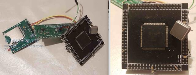 |
||||
| Page 1 of 2 |
|||||
| The Back Shed's forum code is written, and hosted, in Australia. | © JAQ Software 2026 |
