
|
|
Forum Index : Microcontroller and PC projects : E100 LCD Port Tester Thing.....
| Page 1 of 2 |
|||||
| Author | Message | ||||
Grogster Admin Group Joined: 31/12/2012 Location: New ZealandPosts: 9932 |
Hi there.  I have whipped up a simple PCB(all though-hole) to test the LCD port on E100 boards. You plug this board directly into the 40-pin header for the LCD, and run a diagnostic code to light all the LED's. This may be of use to those who want to test that their E100 LCD port is doing what it should be doing, if trying to find out why an LCD on an E100 board is not working as expected. 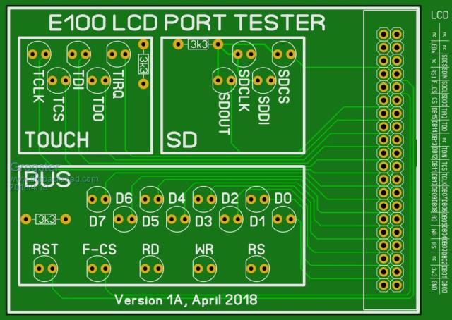 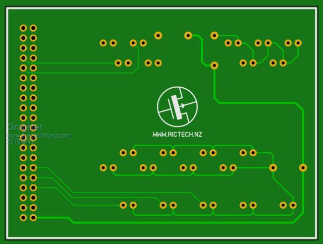 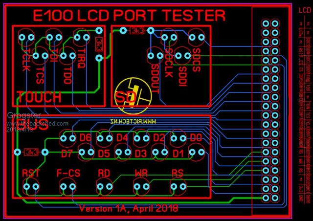 The code(yet to be published here) just switches each LED on one at a time, meaning only one load resistor is needed, although, I have split up the LED's into three different groups. If you run the sequencer fast enough, all the LED's appear to be on all the time, and you can instantly see if any one(or more) LED's are not on, which indicates a problem with the connection to that pin. Alternatively, run the sequencer slowly so you can see each LED turn on and off. This can be very useful to see if you have some shorted pins somewhere, as only ONE LED should be on at any one time, so if you get two(or more), you have shorts to find and fix - that kind of thing. I will be getting some of these made soon, so if anyone wants one, let me know. If there is interest, I will also build a constructors-pack and publish it here so people can make their own if they wish. In my one, I am using 3k3 load resistors, as the LED's I have are super-bright ones. You would probably want to drop that resistor back down to 1k or so for bog-standard LED's...... Smoke makes things work. When the smoke gets out, it stops! |
||||
| antf70 Newbie Joined: 13/07/2016 Location: AustraliaPosts: 20 |
That looks great and would be very useful. Thanks grogster |
||||
| WhiteWizzard Guru Joined: 05/04/2013 Location: United KingdomPosts: 2962 |
Totally agree  I have PM'd you . . . |
||||
| LouisG Senior Member Joined: 19/03/2016 Location: AustraliaPosts: 130 |
Had you considered the use of two DIL 10-LED bars? One could black out unused LEDs with a marker. |
||||
| Bill7300 Senior Member Joined: 05/08/2014 Location: AustraliaPosts: 159 |
and a thumbs up from me too, Grogster. PM on its way. Bill Bill |
||||
| Grogster Admin Group Joined: 31/12/2012 Location: New ZealandPosts: 9932 |
@ LouisG - Absolutely. I even have them in stock, but many people DON'T, so I elected to go with standard 5mm LED's. There were two reasons why I did not use the bar-graph LED things. (1) I stole WW's idea of staggering standard LED's, which makes them easier to follow with your eyes if they are stepping through over having them all in-line. I did not really believe that myself when WW suggested it(in PM's on another project), but once I built a board like that, I had a bit of hat eating to do. WW supplied the hat.  (2) Space was not an issue for standard 5mm LED's, and the PCB would have cost the same weather it was 100x100 or smaller, so there you are. (2) Space was not an issue for standard 5mm LED's, and the PCB would have cost the same weather it was 100x100 or smaller, so there you are. Smoke makes things work. When the smoke gets out, it stops! |
||||
GoodToGo! Senior Member Joined: 23/04/2017 Location: AustraliaPosts: 188 |
Magnificent idea Grogs! Is it possible to incorporate a connector to also plug in standard MM and MM+ LCD backpacks? Ie, the one's that run the 2.8" LCD touchscreen? Cheers, GTG! ...... Don't worry mate, it'll be GoodToGo! |
||||
| Grogster Admin Group Joined: 31/12/2012 Location: New ZealandPosts: 9932 |
An interesting idea. I had not, because the SPI LCD's have many less pins then the parallel MM+ LCD's, so I figured they would be easier to fault-find with less pins. I might have a look at that idea though - there would be room on the PCB. Use one end for the E100's, the other for the SPI LCD's kind of thing. I will have a play with the layout. EDIT: Like this? 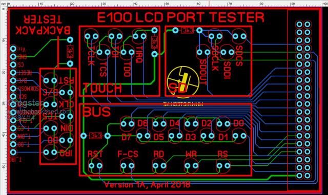 ....and you flip the board 180 degrees to test the SPI LCD's on a MM Backpack or equivalent: 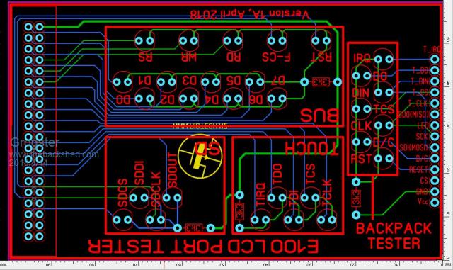 Smoke makes things work. When the smoke gets out, it stops! |
||||
| WhiteWizzard Guru Joined: 05/04/2013 Location: United KingdomPosts: 2962 |
WOW - a great addition that GTG suggested there As per PM, the only thing I can suggest is the inclusion of the 40pin 'Pin Naming' on the silkscreen (but only if it would be readable). Grogs: could you post a 'Green' image of this latest version (as in you original post). This would show clearly the silkscreen / finished-appearance. Thanks  WW |
||||
| TrevorH Senior Member Joined: 06/04/2018 Location: United KingdomPosts: 145 |
Will definitely have one of those, should work on MMX144 as well because pinouts are the same at least for first 8 data lines! Trevor |
||||
| Grogster Admin Group Joined: 31/12/2012 Location: New ZealandPosts: 9932 |
@ WW: Here you are...... 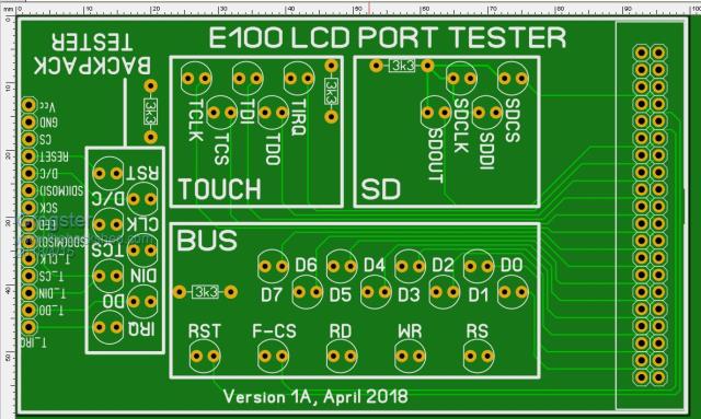 I have looked at the legend for the LCD parallel port, but it's text is only 0.1mm, and Sprint Layout warns that it is too thin/small to come out on the finished board. That legend was only in the image at the top of this thread by mistake, really. I meant to crop it out, as it is outside the actual board size. It was only there to remind me which pin was which when I was routing tracks, so it was never really designed to be on the silkscreen per se'. EDIT: I've had a few PM's and even emails from the website about the price for this board. I can confirm they will be US$5 each INCLUDING airmail postage to anywhere on planet Earth. They are small enough to fit in a standard DLE envelope, so that allows me to send them much cheaper then in any kind of bag or box. Payments via my website, and I will put it up on my site within the next day or two. Boards are now in production. PCB GoGo are very quick. I expect them to be here in about one week from now. I have ordered 20 boards for now, but can easily get more if demand exists. Smoke makes things work. When the smoke gets out, it stops! |
||||
| GoodToGo! Senior Member Joined: 23/04/2017 Location: AustraliaPosts: 188 |
Excellent! Lock me in for one! GTG! ...... Don't worry mate, it'll be GoodToGo! |
||||
| Grogster Admin Group Joined: 31/12/2012 Location: New ZealandPosts: 9932 |
UPDATE: They have landed, and this is what they look like. 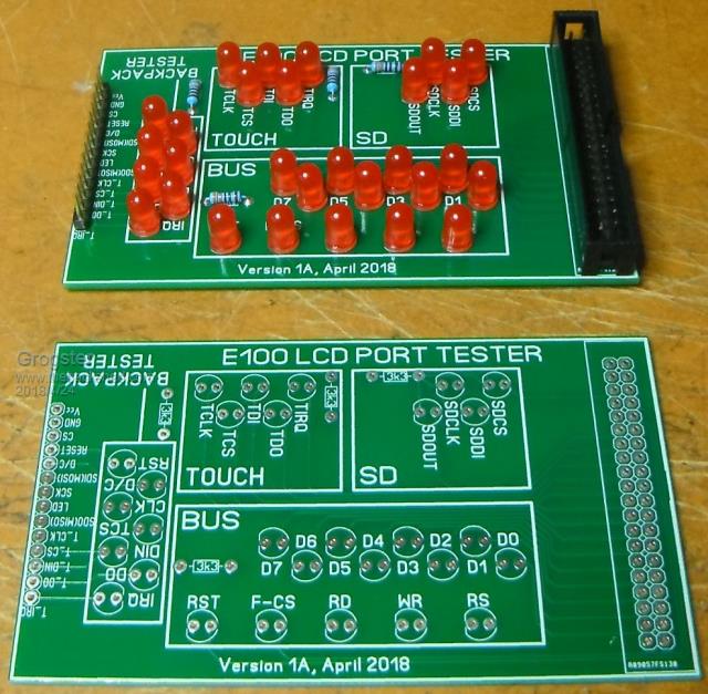 I have to write a simple code to step through the LED's, but hope to do that in the next day or so. Once I have that working, I will post it here. It will be console-menu driven, so you can select which type of unit and area to test. Smoke makes things work. When the smoke gets out, it stops! |
||||
| Grogster Admin Group Joined: 31/12/2012 Location: New ZealandPosts: 9932 |
Here is a short demo video of it working: Wee video... If dropbox asks you to sign up, just close that window, and you should then be able to play the video. It is only a minute or so. Here is the code that makes it work: You MUST disable the LCD, touch and SD card options if you have them set, or when you run this code, MMBASIC will complain the pins are reserved. EDIT: I have just noticed that I have missed the LCD_CS on the Backpack connection. My brain was still in E100-mode, where the LCD is always selected, so CS is grounded and does not need an LED.  Oh well. It would easy to drill a couple of holes in the tester PCB and add that LED. Smoke makes things work. When the smoke gets out, it stops! |
||||
palcal Guru Joined: 12/10/2011 Location: AustraliaPosts: 2039 |
Very handy for anyone making many boards. Paul. "It is better to be ignorant and ask a stupid question than to be plain Stupid and not ask at all" |
||||
| Bill7300 Senior Member Joined: 05/08/2014 Location: AustraliaPosts: 159 |
Not up on your webpage yet, Grogs Bill |
||||
| Grogster Admin Group Joined: 31/12/2012 Location: New ZealandPosts: 9932 |
No, been distracted with HC-12 module and Microchip IPE problems this week! I will get it up there tonight or over the weekend, and will post back when that is done, so you know. Sorry. Smoke makes things work. When the smoke gets out, it stops! |
||||
Quazee137 Guru Joined: 07/08/2016 Location: United StatesPosts: 603 |
Test beds like this are of the greatest helpers in QA and sanity. I have been testing the Hatstands by matherp and a board like this for the RPi's would help in testing Pi-cromite software/hardware. And could cover the large audience of Pi users too. Thanks for always helping solve hardware issues with your boards. Quazee |
||||
| Grogster Admin Group Joined: 31/12/2012 Location: New ZealandPosts: 9932 |
Okey dokey, the board is now available from my website's products page here. Right down the bottom. The tester code is also available for download from the downloads page - linked to in the port tester description. Smoke makes things work. When the smoke gets out, it stops! |
||||
| Bill7300 Senior Member Joined: 05/08/2014 Location: AustraliaPosts: 159 |
Thanks Grogs Bill |
||||
| Page 1 of 2 |
|||||
| The Back Shed's forum code is written, and hosted, in Australia. | © JAQ Software 2026 |
