
|
|
Forum Index : Microcontroller and PC projects : MM Programmer/Debugger 1C...
| Page 1 of 2 |
|||||
| Author | Message | ||||
Grogster Admin Group Joined: 31/12/2012 Location: New ZealandPosts: 9933 |
As a follow-on from the thread about the 1A, here is the latest version: 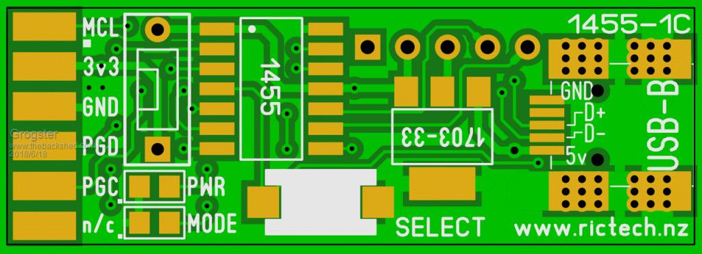 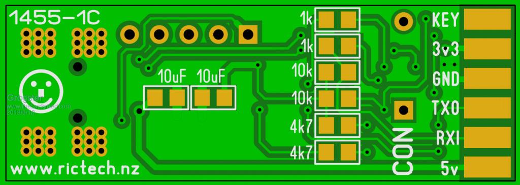 Still a work in progress, but SOIC 1455, DIL switch for 3v3 on/off, 0805 passives, SOT-223 regulator and USB-B socket. ICSP standard pinout on one side of the unit, and console connection on the other. Still fine-tuning the layout, but this is the new design. Smoke makes things work. When the smoke gets out, it stops! |
||||
Azure Guru Joined: 09/11/2017 Location: AustraliaPosts: 446 |
I think I am missing something re the 3v3, 5v no power options. I understand the chip is only programmed at 3v3, but if you are running the board using the comms side would you not want the option to power the target board (probably with its own onboard 5v to 3v3 regulator). If it is fed through the 5v from the USB there should be enough to even power an onboard LCD on the target. Like I said I am probably missing something, but I see that as very useful especially for initial configuration and testing of the taregt using the serial comms after the chip is programmed. |
||||
| Grogster Admin Group Joined: 31/12/2012 Location: New ZealandPosts: 9933 |
In that event, switch OFF the 3v3 DIL switch, and use the 5v supply on the console side of the PCB. Done.  Smoke makes things work. When the smoke gets out, it stops! |
||||
CircuitGizmos Guru Joined: 08/09/2011 Location: United StatesPosts: 1427 |
Looks nice. You do good work, Grogs. Micromites and Maximites! - Beginning Maximite |
||||
| Grogster Admin Group Joined: 31/12/2012 Location: New ZealandPosts: 9933 |
Thanks. I will be ordering some of these later this week. I will also prepare a constructors pack with the gerbers etc, so that anyone who wants to, can get their own ones made. Smoke makes things work. When the smoke gets out, it stops! |
||||
| erbp Senior Member Joined: 03/05/2016 Location: AustraliaPosts: 195 |
Hi Grogs. I am wondering what is the status of the 1C version of this board: Did it ever progress to production? If yes, are you planning to sell it? If so - what options - bare board only, unassembled kit containing the board plus all parts and/or fully assembled module? Cheers, Phil. |
||||
| Grogster Admin Group Joined: 31/12/2012 Location: New ZealandPosts: 9933 |
Hi there. Thanks for asking.Yes, I have the prototype PCB's here, but I have not yet built one. Assuming it works OK, then I will probably offer both an assembled module and a kit on the website. Smoke makes things work. When the smoke gets out, it stops! |
||||
| erbp Senior Member Joined: 03/05/2016 Location: AustraliaPosts: 195 |
Cool, thanks. I'll check your website from time to time for an update. Phil. |
||||
| Grogster Admin Group Joined: 31/12/2012 Location: New ZealandPosts: 9933 |
I will keep this thread updated when I have built and tested the new prototype, so just watch this thread.  Smoke makes things work. When the smoke gets out, it stops! |
||||
| Grogster Admin Group Joined: 31/12/2012 Location: New ZealandPosts: 9933 |
I have finally managed to build this. It works, and Windoze sees it fine as per all 1455 chips. 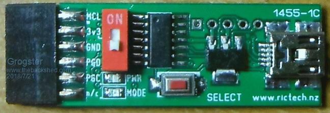  Smoke makes things work. When the smoke gets out, it stops! |
||||
| robert.rozee Guru Joined: 31/12/2012 Location: New ZealandPosts: 2502 |
hmmm, there may be a slight problem. the ground connection for the two 10uF filter capacitors (that should be 4.7uf to keep within the USB specs, btw) seems to be entirely through a sliver of ground fill. you may wish to add an offcut of resistor lead from the junction of the two capacitors to the cluster of vias just above the word "rictech". cheers, rob :-) |
||||
| Grogster Admin Group Joined: 31/12/2012 Location: New ZealandPosts: 9933 |
Well spotted! I will alter that to give more copper ground plane for the caps, and change the silkscreen to 4u7. Smoke makes things work. When the smoke gets out, it stops! |
||||
| robert.rozee Guru Joined: 31/12/2012 Location: New ZealandPosts: 2502 |
you may be able to just add a ground via: 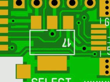 the other side should come out close to the junction of the caps. cheers, rob :-) |
||||
| erbp Senior Member Joined: 03/05/2016 Location: AustraliaPosts: 195 |
Or another possible solution requiring less adjustment to the board layout - add a via to the right of the 1703 regulator tab as shown below. This should connect to the ground copper below the capacitor closest to the USB connector, approximate position as also shown below. 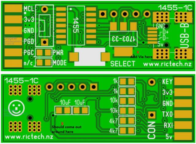 Regards, Phil. |
||||
| Grogster Admin Group Joined: 31/12/2012 Location: New ZealandPosts: 9933 |
All of these suggestions have been taken on board(pun!), and this is what we now have:  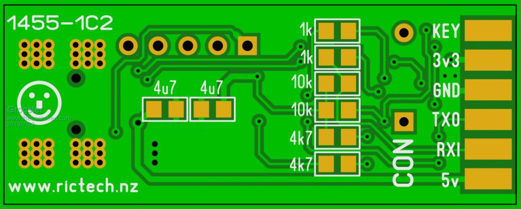 Smoke makes things work. When the smoke gets out, it stops! |
||||
| Geoffg Guru Joined: 06/06/2011 Location: AustraliaPosts: 3353 |
Sorry but I have missed this somewhere. What does the switch do? Geoff Graham - http://geoffg.net |
||||
| paceman Guru Joined: 07/10/2011 Location: AustraliaPosts: 1329 |
Grogs, would it be worthwile adding through-holes on each of the ICSP tabs to optionally allow 'normal' headers to be used. That would allow it to be used flat on a breadboard, single or double pin-wise - or any other orientation people might want. Greg |
||||
| erbp Senior Member Joined: 03/05/2016 Location: AustraliaPosts: 195 |
@Geoffg The switch allows you to disconnect the 3v3 supply from the 3v3 pins on the connector, primarily to make it easy to use the ICSP side of the connector to program a chip that is mounted on a pcb that has its own power supply and may have other components connected that would overload the regulator on the Programmer/Debugger board. Regards, Phil. |
||||
| Azure Guru Joined: 09/11/2017 Location: AustraliaPosts: 446 |
Not sure how that would be done given they are at the same place on the PCB on opposite sides. |
||||
| Grogster Admin Group Joined: 31/12/2012 Location: New ZealandPosts: 9933 |
@ Azure and paceman: Can't be done, as Azure says, due to the pads on the other side. Mounting to a breadboard is as easy as just plugging it into some long pin-strips - problem solved. You could even use right-angled pin-strips if you wanted it laying flat - sticking up problem solved. Smoke makes things work. When the smoke gets out, it stops! |
||||
| Page 1 of 2 |
|||||
| The Back Shed's forum code is written, and hosted, in Australia. | © JAQ Software 2026 |
