
|
|
Forum Index : Microcontroller and PC projects : LCD Screen Corruption
| Page 1 of 2 |
|||||
| Author | Message | ||||
| Phil23 Guru Joined: 27/03/2016 Location: AustraliaPosts: 1667 |
Hi All, Every so often I'm getting a corrupted LCD display on my heat controller. The code in the MM is still running fine if I check at the console & a reboot or Ctrl-C & run again fixes it, but it's obviously annoying... Any suggestions at a hardware or software level for a quick solution. Cables coming from the board got to a string of DS18B20's on the left plug & the other two (3) got to 2x 4 gang relay boards up in the roof. Any suggestions? Thanks Phil. Edit, The thought in software as a temporary fix would be to reset the LCD periodically; Not sure how to do that.... 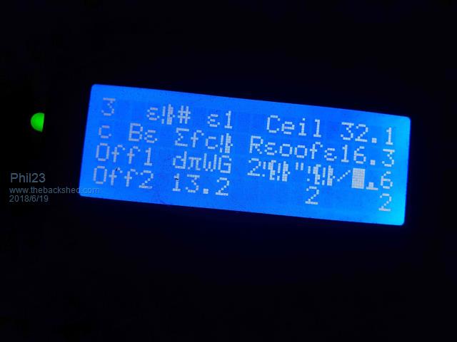 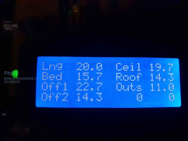  |
||||
Azure Guru Joined: 09/11/2017 Location: AustraliaPosts: 446 |
I see you have a couple of electro caps on the board. Being Veroboard the actual signal/voltage at the component pin may fluctuate from what you would expect. If you have an oscilloscope you can check the noise on the 5v directly at the LCD while it is running. Possible some ripple or HF noise effecting it. It would pay while you are doing that to also check the control and data signals at the LCD to make sure they are also nice and clean. You should try and monitor the signals during worst case conditions, when relays are switched and when the wireless unit is transmitting/receiving. |
||||
CircuitGizmos Guru Joined: 08/09/2011 Location: United StatesPosts: 1427 |
Try an LCD INIT command frequently. Perhaps every time you clear the display. Micromites and Maximites! - Beginning Maximite |
||||
| Phil23 Guru Joined: 27/03/2016 Location: AustraliaPosts: 1667 |
That thought did come to mind, but when I tried it, it returns [Code] LCD INIT 23, 24, 25, 26, 15, 16 Error: Already open >[/code] I suppose I could do a temp cludge like this periodically. [Code] LCD Close LCD INIT 23, 24, 25, 26, 15, 16 [/code] But also wonder if I can send a reset command with one of these statement. 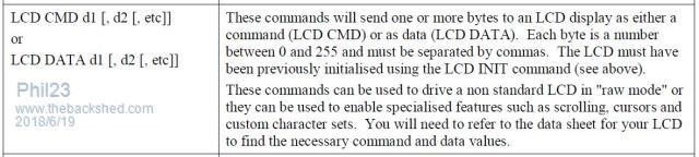 |
||||
| Azure Guru Joined: 09/11/2017 Location: AustraliaPosts: 446 |
Are you able to check things with a scope or is that not possible? A multimeter will not really show what you need to see. My suspicions would be firstly around power quality at LCD from noise or excessive ripple or dips during certain operations on power lines at LCD. If you can't check it and just want to try things a 100uF/220uF electro and a 0.1uf ceramic wired close to the LCD power pins may help clean up and stabilise the power at the LCD. The WiFi board is probably the biggest power consumer during transmission after the relay board. The Control and Data lines really need a scope on them to see if they are clean. On your board it looks like they are wired in fairly directly so they should be ok. |
||||
Chopperp Guru Joined: 03/01/2018 Location: AustraliaPosts: 1123 |
You'll probably need to keep the data lines to the display as short as possible. I did a PICAXE project a while ago with a 16x2 display connected by a ribbon cable. Played up a lot. Tried all sorts of shielding arrangements including a wrap around ferrite type shield covering most of the cable. Reduced the problem quite a bit. Unfortunately, it did not occur to me at the time to arrange for an LCD reset rather than restarting the whole lot. I've also got an LCD on a Maximite & one on a uMite which occasionally go funny. Both of these have a switch to signal the software do an LCD CLEAR & then an LCD INIT as suggested in previous posts. I did at one stage have periodic CLOSE & INIT coded into the software. Good luck  ChopperP |
||||
| ajkw Senior Member Joined: 29/06/2011 Location: AustraliaPosts: 290 |
How often do you write to the LCD? Do you write only when something has changed or every time in a loop? I have found you can bother them if you write continuously. I have also had a 12V boat bilge pump that was other side of a opto-coupled relay make enough noise back through the power system to cause simular garbage on the LCD, a electro-cap on the wires to the pump helped. Project link - https://www.thebackshed.com/forum/forum_posts.asp?TID=7557&KW=ajkw |
||||
| Phil23 Guru Joined: 27/03/2016 Location: AustraliaPosts: 1667 |
Have a DSO138 LCD thingy; only audio range, but still useful. That & a 20Meg Hantek USB; just need to load S/W on this laptop & reach 2 foot sideways. Phil. |
||||
| Phil23 Guru Joined: 27/03/2016 Location: AustraliaPosts: 1667 |
I have a Timer variable that updates the display every 1 second. [code]TimerLCD=Timer .. .. .. IF Timer>TimerLCD+1000 Then Go & update the LCD & reset TimerLDD to Timer again... .. .. [/code] |
||||
| ajkw Senior Member Joined: 29/06/2011 Location: AustraliaPosts: 290 |
Once a second should be fine. As I said noise was a problem on the power supply from the pump in my project. Somewhere I should have a couple of spare boards from my project that I had made, I designed it as a 'backpack' for a 16x2 and will also cope with a 20x4 LCD. It does use the 'default' LCD pin out while you appear to use other pins, anyway, if you are interested I'll post a pic. Anthony. |
||||
| Azure Guru Joined: 09/11/2017 Location: AustraliaPosts: 446 |
Have a try using the DSO138, it is only 5V and hopefully it will show you if the LCD Vcc and Gnd lines are clean or have ripple/noise on them. It should also show you if the data and control lines are clean since they are fairly low speed signals. I still suspect something like when it is transmitting it's causing noise or a dip in either or both the LCD power and data/control signals. |
||||
bigmik Guru Joined: 20/06/2011 Location: AustraliaPosts: 2979 |
Hi Anthony, Try fitting 10k pull-ups on the data and control lines.. Also try updates every 5sec. As a test to see if it is amount of updates.. Mik Mick's uMite Stuff can be found >>> HERE (Kindly hosted by Dontronics) <<< |
||||
| bigmik Guru Joined: 20/06/2011 Location: AustraliaPosts: 2979 |
Hi Anthony, You could also be getting interference from your wireless radio transmitter card.. try removing it and see if that is the cause, Mik EDIT *** Is the display a 5v unit or 3v3 unit? What voltage is it running off? If a 5v unit running off 3v3 that might be your issue. Mik Mick's uMite Stuff can be found >>> HERE (Kindly hosted by Dontronics) <<< |
||||
| ajkw Senior Member Joined: 29/06/2011 Location: AustraliaPosts: 290 |
Hey Mick, Phil is OP. Anthony. |
||||
| Phil23 Guru Joined: 27/03/2016 Location: AustraliaPosts: 1667 |
Lol Mik, You are as bad with names as I am.... Phil. PS, Can you supply a small BOM of part for a few of your boards I haven't finished yet? Just a few SMD bits. |
||||
| bigmik Guru Joined: 20/06/2011 Location: AustraliaPosts: 2979 |
Sorry Anthony, I must be getting old... 3 months and 1 day from now I will be retiring (or at worst a few weeks more). Looking forward to playing more with my mites again. Mik Mick's uMite Stuff can be found >>> HERE (Kindly hosted by Dontronics) <<< |
||||
| Phil23 Guru Joined: 27/03/2016 Location: AustraliaPosts: 1667 |
Agree with all that a hardware issue exists, and will try all the suggestions above. In the short term though, just the software reset will remove the annoyance. This project is far from finished from a code point of view & at this point in winter, after it boots, I manually change a few options to pump warm air to my office. If the display corrupts, it still runs & I still have a perfectly operational VT display & interface available on any PC via Wifi. It's just annoying looking at the corrupted screen as I walk past. If I hit the reset & get the display back, I loose any manual overrides I made on the dampers & fans, so would need to go to a PC & set them again.... Current uptime is 15 hours & there was no corruption last time I looked, but see 2 recalcitrant characters just now. So till I get to the board, probably the best (bad) idea is an interrupt sub that tidies it up ever 2 or 3 minutes, regardless of whether its corrupted or not. It's just a matter which is the best bit of code to do it? LCD CMD or LCD DATA & what to send. Phil. |
||||
| CircuitGizmos Guru Joined: 08/09/2011 Location: United StatesPosts: 1427 |
Info here: http://web.alfredstate.edu/faculty/weimandn/lcd/lcd_initialization/lcd_initialization_index.html Here: http://www.microcontrollerboard.com/lcd.html From rusty memory, I sent 30h several times to the display, followed by 01h. Your 4 line will be slightly different. Micromites and Maximites! - Beginning Maximite |
||||
| Phil23 Guru Joined: 27/03/2016 Location: AustraliaPosts: 1667 |
Just tried breaking to a prompt when I had just two characters of corruption, sent in LCD CMD &h30 & it cleared the 2nd & 4th line & put more gobbly gook in lines 1 & 3. Tried LCD 1,1,"hello" after that with no response. Should have tried "hello" in a few places first, to see if it was still operational, as I'm assuming it's not, cause if it was each re-write should get rid of the corruption. Need to find a list of the valid commands... |
||||
| CircuitGizmos Guru Joined: 08/09/2011 Location: United StatesPosts: 1427 |
I'm really sorry if I gave you the impression that there is one byte to send to reset the display. Display init is a sequence of bytes, like the two linked pages show. Micromites and Maximites! - Beginning Maximite |
||||
| Page 1 of 2 |
|||||
| The Back Shed's forum code is written, and hosted, in Australia. | © JAQ Software 2026 |
