
|
|
Forum Index : Microcontroller and PC projects : micromite repeatedly restarts itself
| Page 1 of 2 |
|||||
| Author | Message | ||||
| factotum Newbie Joined: 29/10/2017 Location: United KingdomPosts: 18 |
A veroboard which normally works fine has developed a habit of sometimes working ok and sometimes going into a loop in which the MM interpreter repeatedly restarts itself, printing: Micromite MKII MMBasic Ver 5.03.02 Copyright 2011-2017 Geoff Graham repeatedly. It can be stopped by hitting contol-C, but the looping resumes after RUN. It has correct 47uF decoupling capacitor. The restart line, pin 1, is wired to V+ via a 10K resistor and is otherwise not connected to anything. V+ is 3.3 volts. The program is not executing any END command. Any ideas what could be causing this? |
||||
goc30 Guru Joined: 12/04/2017 Location: FrancePosts: 435 |
hi I had this probl�m whith ArmMite and voltage regulators like "7805" family and input power high (14v). When regulator become too hot, proc go to loop. after that I have change my power and it is better |
||||
| factotum Newbie Joined: 29/10/2017 Location: United KingdomPosts: 18 |
goc30, thanks. But my voltage is ok at 3v3 to the MM (regulated down from 5v). But perhaps I should look at V+ on a scope to see if spikes or drop outs. |
||||
| WhiteWizzard Guru Joined: 05/04/2013 Location: United KingdomPosts: 2962 |
Hi Factotum, Any chance you can post a photo? What type of Cap are you using? Is it a Tantalum or a ceramic? If it is an electrolytic then that could be your problem. What vReg are you using? Any caps on it's In and Out? WW |
||||
| factotum Newbie Joined: 29/10/2017 Location: United KingdomPosts: 18 |
WhiteWizzard - Yes, well when I designed this layout it was fairly clean and logical, but I have had to make so many addons and mods over the past year that it is now a right mess! That might be the cause in fact. 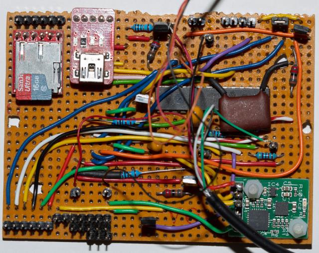 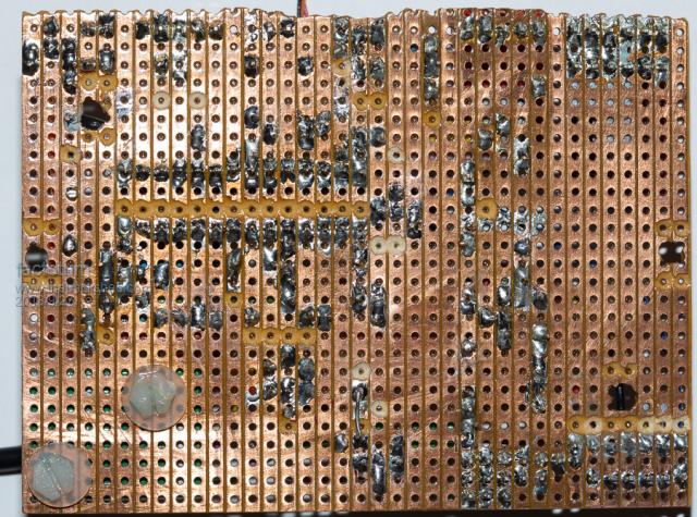 These photos are missing the 10K resistor to pin 1 as I just decided to replace it and resolder. Board is covered in a conformal coating (it goes in a model boat in an IP68 box), which I have to scrape off every time I change anything. Decoupler is tantalum. The Vreg is built into the USB-to-serial converter seen to the right of the microSD card. I power this from USB when testing but from lithium power pack when sailing. This 3v3 only feeds the MM. Lots of stuff on MM: serial line from GPS unit, I2C from compass/gyros, SPI from shaft encoder, A-to-D from power voltage, other pins sensing digital data or pulse length (from anemometer), the SD logger hanging on console output, as is a LoRa transmitter (via a fet switch). Probably not much you can say other than "It's a mess, what do you expect?"! |
||||
| WhiteWizzard Guru Joined: 05/04/2013 Location: United KingdomPosts: 2962 |
OK - I initially thought it was because you were drawing too much power from the 3v3 output on the USB-to-UART module - however, you say that you're only powering the MM from this 3v3 rail. Note: The 3v3 output is good for about 50mA; any more and you will starting causing power glitches (resulting in the MM resetting). In your original post, I mis-understood your comment 'otherwise not connected to anything'. I incorrectly assumed the MM was not connected to anything other than the 'basic' circuit (i.e. 10K resistor and 10uF vCap). Seeing the photo has helped (sort of!) in highlighting the potential issue: IF it is only resetting 'sometimes' - is it when your program is running? If so, you could have a logic-level conflict occur somewhere in your code i.e. you set a pin to a low output when at some stage the pin becomes a high level. Prevent your code from running (possibly need to turn AUTORUN OFF to help) and leave the MM effectively at the Command Prompt. Type EDIT, then hit ESC (to exit EDITor) and this will 'reset all I/O pins. Then simply leave everything as long as possible and see if the MM resets itself. If it does, then it is likely a power issue. IF however it doesn't reset, then it is likely a coding issue (level-conflict). Hope the above kind of makes sense; and more importantly helps you diagnose the issue . . . |
||||
| factotum Newbie Joined: 29/10/2017 Location: United KingdomPosts: 18 |
Thanks. I don't think it loops when at the command mode. It has to be running to fail. Also, it doesn't seem to fail when program is in a PAUSE (which kind of rules out a power problem?). I took the board out of the box and unplugged everything except the gps serial unit, because program quickly ENDs with an error message if GPS isn't there. It still loops. Found a place where a tap, or a very light flexure of the board, causes the problem. Pressing on the other side of the board removes the problem (for a while). But under a X10 magnifier I can't see any dry joints or hairline cracks in copper. Think I'll sleep on this, it's beginning to drive me nuts! I'm beginning to wonder if the problem might be in the MM chip itself (i.e. that I might have damaged it by mechanical handling of the board when I scrape off the conformal coating to make mods - have to push quite hard). |
||||
| panky Guru Joined: 02/10/2012 Location: AustraliaPosts: 1120 |
@factotem, With respect, there are some pretty dodgy looking joins on your veroboard, I would start as a minimum, re-soldering all the MM pins and then inspecting them under a magnifying glass. If flexing the board is causes the problem then this just highlights my suggestions above. By the way, bin where you are myself and it can be frustrating  - stick with it and I am sure you will get it going. - stick with it and I am sure you will get it going.  panky. ... almost all of the Maximites, the MicromMites, the MM Extremes, the ArmMites, the PicoMite and loving it! |
||||
Azure Guru Joined: 09/11/2017 Location: AustraliaPosts: 446 |
Nice project. I agree with Panky. I would resolder the MM pins for a start. I would also resolder the joints from the power source(s) to the MM chip and consider adding a bypass cap on the 3.3v as close to the MM as you can. As you have expanded the circuit over time any noise and intermittent power used from the peripherals may be causing a voltage dip at the power pins on the MM. Check what conformal coating you are using, some are able to be soldered through so you don't need to scrape it away to do any mods/changes. Also some have a remover that you can spray it with and give it a brushing/wash to remove the coating before working on it. If you have to remove it make sure you also give it a good scrub with PCB cleaner or isopropyl before soldering to clean up the joints and make for easier soldering. Use a good flux based solder and even dab the points to solder with a flux pen to make the solder flow nicely. Afterwards clean any flux residue with PCB cleaner or isopropyl (which it looks you have been doing) before touching up or reapplying the conformal coating. Good luck with it, with a little patience you will track down the cause, keep us posted or ask more questions. |
||||
| Geoffg Guru Joined: 06/06/2011 Location: AustraliaPosts: 3353 |
Reloading the latest MMBasic or resetting to defaults (page 16 of the manual) might stop the restarts. It is possible that MMBasic has been confused with conflicting option settings. Geoff Graham - http://geoffg.net |
||||
| CaptainBoing Guru Joined: 07/09/2016 Location: United KingdomPosts: 2171 |
+1 re-flash the processor. At least then you are starting from a good known. |
||||
| factotum Newbie Joined: 29/10/2017 Location: United KingdomPosts: 18 |
Thanks for all the above. I'll get to work on it. I agree some of the soldering looks horrid. Partly it's because veroboard holes are too big for most modern lead sizes, and I generally don't use so much solder as to fill up those holes. Also, I have bought connecting wire off ebay and some of it doesn't tin at all easily - bad decision. Coating is this. Datasheet doesn't say if can be soldered through but I tried it and wasn't happy with results. Also, don't think it has a matching removal substance. Penalty of choosing something that does a good job! I think I'll try sucking all the solder off the MM ic, cleaning up, and soldering in a different one, thus killing several birds with one stone. Think I have to order a Pickit3 to reflash? On finding it touch sensitive, I thought I could localise fault by carefully poking around (I'm using a long plastic tuning wand). But unfortunately that approach doesn't get any closer. Now need a bit of time to work through these suggestions. |
||||
| WhiteWizzard Guru Joined: 05/04/2013 Location: United KingdomPosts: 2962 |
Can I suggest you get hold of a MicroBridge . This acts as a PicKit3 (and also a USB-to-UART) - much more useful; and a LOT cheaper!  |
||||
| Azure Guru Joined: 09/11/2017 Location: AustraliaPosts: 446 |
Here is one I quickly found from RS that you can solder through. I second the Microbridge over a pickit3 or 4 (I have both and much prefer the microbridge). Much ore useful, cheaper and easy to program MM or use it for the console serial interface. WhiteWizzard can supply them locally (in the UK) from his site at micromite.org |
||||
| Geoffg Guru Joined: 06/06/2011 Location: AustraliaPosts: 3353 |
Resetting to the defaults (page 16 of the manual) does not require a programmer and would be worthwhile trying while you are waiting for the programmer. It could be a corrupted firmware and in that case you will need a programmer. Geoff Graham - http://geoffg.net |
||||
| factotum Newbie Joined: 29/10/2017 Location: United KingdomPosts: 18 |
Thanks all. MicroBridge it is then, when I need it. Problem with some of those RS conformal coatings is that for peculiar Health & Safety resons they will only sell them to companies. Meanwhile I've removed the MM ic, cleaned up, and soldered in another one I had, thus dealing with any alleged dry joints plus firmware problems. Unfortunately, the tap sensitivity problem persists. However, I am working through other anomalies systematically, using a simpler test program in the MM, and hopefully will eventually home on this. At the moment the program inexplicably ENDs itself on the line IF PIN(CTSpin)=1 AND tel=1 THEN PIN(TELpin) = 1 ELSE PIN(TELpin) = 0 where TELpin is 2 and CTSpin is 16. Of course, this code worked perfectly before and "I haven't changed anything"! I just need some time to work on this. |
||||
| WhiteWizzard Guru Joined: 05/04/2013 Location: United KingdomPosts: 2962 |
Out of interest, you say that TELpin is pin 2 - is that correct? Pin 2 is next to Pin 1 (i.e. the Reset pin) Can I suggest that at the Command Prompt you type the following: SETPIN(2),dout PIN(2), 0 Does this second command reset your MicroMite? If it does then you have a short between Pins 1 & 2 WW |
||||
| factotum Newbie Joined: 29/10/2017 Location: United KingdomPosts: 18 |
WhiteWizzard - Good thought. I couldn't see a short. Looking at pin 1 on a scope did not seem to show anything awry: 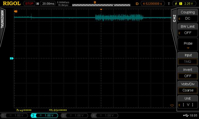 But I did have two blue wires going to a jumper top right on the board, and they ran parallel to the 10k resistor on pin 1, and they carried console transmitted data. I decided to move the jumper elsewhere and get rid of those blue wires. And the problem has gone away. No more tap or flex sensitivity. No more restarting. Still not totally sure of the cause. But happy it's no longer there. Thanks to all. |
||||
| factotum Newbie Joined: 29/10/2017 Location: United KingdomPosts: 18 |
Hmm. I spoke too soon. It is still tap sensitive. And it's still looping sometimes. And it sometimes doesn't start at all on power up - until I tap it. God this is a pain! |
||||
| factotum Newbie Joined: 29/10/2017 Location: United KingdomPosts: 18 |
Finally managed to get a scope on it when it was reliably looping. Pins 13 and 1 ok, but pin 28 (analog V+) had about 1.4 volts of noise on it. This enabled me to find a dry joint between pin 28 and the 3v3 power. Not totally clear why noise on the analog power should affect digital operation of the MM, but it seems it did. I think it is ok now, but not going to claim that until more testing, in view of false alarm earlier. |
||||
| Page 1 of 2 |
|||||
| The Back Shed's forum code is written, and hosted, in Australia. | © JAQ Software 2026 |
