
|
|
Forum Index : Microcontroller and PC projects : CMM2 - Maximite2 Kit v3.0 PCB build notes
| Page 1 of 5 |
|||||
| Author | Message | ||||
| Womble Senior Member Joined: 09/07/2020 Location: United KingdomPosts: 267 |
Greetings Everyone ... I am a new forum member, and have just completed my Maximite2 kit 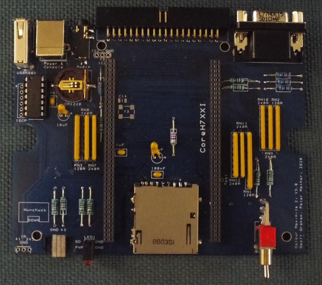 For the benefit of anyone who is also building one of these, here are some notes I made on the process ... 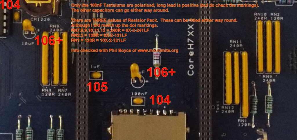 Maximite 2 Kit v3.0 PCB from www.micromite.org (Phil Boyce in the UK) https://micromite.org/shop/maximites/colour-maximite/colour-maximite-2-kit/ This is the v3.0 PCB with the resistors replaced by Resistor Packs Only the 100nF Tantalums are polarised, long lead is positive (but do check the markings). The other capacitors can go either way around. Capacitor Markings: 10uF = 106+ (polarised Tantalum) 100nF = 104 (can go either way round) 1uF = 105 (can go either way round) There are THREE values of Resistor Pack. These can be fitted either way round. 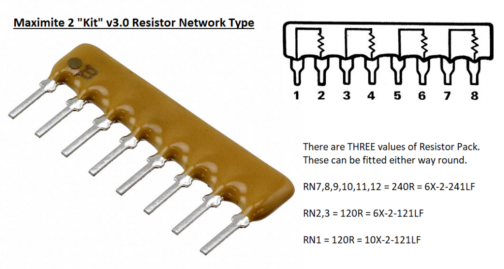 Although I did match up the dot markings. RN7,8,9,10,11,12 = 240R = 6X-2-241LF RN2,3 = 120R = 6X-2-121LF RN1 = 120R = 10X-2-121LF UK Ebay links for the Waveshare and Headers: Here are the ebay links I used. Waveshare and Headers (pack of 10) ordered on 24th June 2020. Headers arrived on 3rd July 2020 eBay item number: 292145372983 https://www.ebay.co.uk/itm/10x-Pitch-2-0-2mm-2x40-Pin-80Pin-Female-Double-Row-Straight-Pin-PCB-Header-Strip/292145372983?ssPageName=STRK%3AMEBIDX%3AIT&_trksid=p2057872.m2749.l2649 Waveshare arived on 7th July 2020 (because the postman missed me on the 4th) eBay item number: 153758141729 https://www.ebay.co.uk/itm/Waveshare-STM32H743IIT6-MCU-Core-board-full-IO-expander-JTAG-SWD-debug-interface/153758141729?ssPageName=STRK%3AMEBIDX%3AIT&_trksid=p2057872.m2749.l2649 The machine lives  Board fired up yesterday, and case completed today. I have been hacking around with some of the demo code trying to get a feel for this dialect of Basic. Still a few teething problems. I'm getting some noise on the video output, which may be down to my monitor, and some interference in the audio playback which seems to be picking up distortion from the video output. However so far I am very pleased with the build. Many thanks to the Dev Team for an excellent little computer. Regards Roy (The Womble) |
||||
| Womble Senior Member Joined: 09/07/2020 Location: United KingdomPosts: 267 |
Regarding SD Card wierdness ... On my machine I was having problems with the SD Cards not being detected. Sometimes they worked, sometimes nothing showed up  F1 to open file browser ... may show nothing and an error message is displayed I am running version CMM2V5.05.03.bin firmware from the CMM2_Construction_Pack.zip I appreciate that there are newer firmwares out there I found that setting OPTION SD TIMING CONSERVATIVE fixes this on older firmware versions (eg. CMM2V5.05.03.bin) 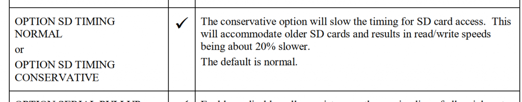 I am told this is due to be changed on future releases, and will default to this (but called NORMAL) |
||||
TassyJim Guru Joined: 07/08/2011 Location: AustraliaPosts: 6549 |
It's good to see some images of the V3 motherboard. You mention polarised capacitors: That should read only 10uF are polarised. Also, If you install the latest firmware, it defaults the what was "OPTION SD TIMING CONSERVATIVE" with the alternative option of "FAST" available. There are other bug fixes so I would recommend using the latest firmware, especially at this early stage of the journey. Jim VK7JH MMedit |
||||
| Womble Senior Member Joined: 09/07/2020 Location: United KingdomPosts: 267 |
My bad , I wrote these notes the day after I built the thing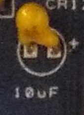 10uF Tantalums are provided in the kit Many thanks for your comments Jim. I was thinking of trying a later firmware version tomorrow, I started out with CMM2V5.05.03 simply as a test as it was provided in the construction pack. I am getting some wierd video and audio noise interference, and am planning a more thorough test session tomorrow. Hang onto your hats boys ... this is going to be a fun ride  |
||||
| abraxas Regular Member Joined: 16/06/2020 Location: CanadaPosts: 99 |
Interesting stuff about your video noise issue. I have a Waveshare based CMM2 that I bought from Circuit Gizmos. It shipped with a 400MHz Waveshare board so I ordered a 480 MHz one to upgrade. I received the second Waveshare board yesterday and experienced video noise issues with it. I tried the latest stable firmware and the latest beta and having the same issue where the 400MHz board gives a clear image but the 480MHz one has noise issues especially with light background. It's actually more like slightly moving horizontal distortion rather than noise but it is consistent and persistent. Looks like CMM2 is not tuned well for the 20% higher clock rate? That or the Waveshare boards are not of very consistent quality. |
||||
| Womble Senior Member Joined: 09/07/2020 Location: United KingdomPosts: 267 |
This sounds familiar ... My Waveshare is a 480Mhz board. It appears more in higher resolution modes. My comments about RF Shielding refer to a video by Neil from Retro Man Cave who found that adhesive copper tape greatly improved video output on a cheap chinese vga converter where the noise was being generated from the RAM bus. https://www.youtube.com/watch?v=xqlrOcGZx38 Refers Given that this is a non destructive mod ... I may experiment There are very many datalines running underneath the Waveshare  Comments from the more electrically savvy forum contributors would be welcone. I expect the audio noise is caused by similar interference. For example: This program (which I Wombled for test purposes from this forum) certainly does not include any audio ... but clicks on every frame ... go figure  The clicking actually adds to the coolness of this program, but its not supposed to be there. Kudos to the author, this is a cool demo. Help and comments appreciated as always. |
||||
| TassyJim Guru Joined: 07/08/2011 Location: AustraliaPosts: 6549 |
abraxas, I can't see any video interference with either of my Waveshare boards 400 or 480 MHz. I do have some RF emissions from the board, especially since I changed to a 8MHz oscillator in place of the crystal. It is not enough to cause any interference to the audio or video, just audible when listening to my Amateur radios. I suggest you try a video lead with suppressors fitted. Likewise, a RF suppressor on the audio and USB leads is a good investment. Jim VK7JH MMedit |
||||
| Womble Senior Member Joined: 09/07/2020 Location: United KingdomPosts: 267 |
Abraxas ... try something with audio ... is the sound output clean, or is there distortion/interference? I would be interested to hear your experience. |
||||
| Womble Senior Member Joined: 09/07/2020 Location: United KingdomPosts: 267 |
Already tried that ... ferrite cores on both the audio and vga leads. I will test with multiple vga displays and cables tomorrow. Watch this space ... |
||||
| Womble Senior Member Joined: 09/07/2020 Location: United KingdomPosts: 267 |
BTW ... I'm not knocking an awesome design I fully expect that my problems are self caused. Wombles (being a form of stuffed toy) have kapok for brains. I keep thinking ... what have I done wrong ? Edited 2020-07-12 12:36 by Womble |
||||
| GregZone Senior Member Joined: 22/05/2020 Location: New ZealandPosts: 114 |
Interesting. I didn't even know there was a V3.0 PCB? Are the resistor packs the only change? Or, are there other updates on the V3.0 PCB? Personally, I think I prefer the older V2 PCB using 1205 SMD resistors. Although not TH, the 1205's are easy enough to hand solder. But the resistor packs do look a whole lot better than vertically mounted individual TH resistors! Definately get onto the latest BETA firmware. I was also bitten by the SD issue until someone pointed out CONSERVATIVE option. Much better now that the default is the marghinally slower (but seemingly more compatible) speed, and those wanting to experiment with faster speed can try FAST. |
||||
| Womble Senior Member Joined: 09/07/2020 Location: United KingdomPosts: 267 |
I ordered my kit before it appeared on the webise at micromite.org For a ham fisted solderer like me the resistor packs are a godsend � Unsure if there are any other changes ... does not look like any from examining the schematics. I'm going to install one of the beta firmwares tomorrow, now I have a working MCP2221A A very nice chap clued me in on the SD issue ... shout out to Phil Boyce (aka WhiteWizzard ... Hope I got that right) I cannot recommend the service received from micromite.org highly enough ... Exemplarary Edited 2020-07-12 12:57 by Womble |
||||
| KeepIS Guru Joined: 13/10/2014 Location: AustraliaPosts: 2203 |
I have no clicking audio running that wire frame ball demo. Music mp3 files sound fine. I guess you know that the audio from the DAC is not AC coupled and will not drive low impedance loads, obviously doing that would cause clipping, especially if the volume is wound up. 480MHz waveshare board. Mike. NANO:Inverter V 8.2ks - Linux AvrDude GUI script V4.1 |
||||
| KeepIS Guru Joined: 13/10/2014 Location: AustraliaPosts: 2203 |
I note that the MB you have has been redesigned to accommodate resistor arrays, therefore the layout of the digital lines is different from the standard WS MB that I'm using, not saying there is anything wrong, it may be better, just a difference. I know that layout definitely contributes to noise in 800x600 modes. I proved that when I had my WS module wired up with short leads tacked onto the top of the PCB connectors (top of the WS board) as no sockets or MB were available at the time. In that test setup there was a small amount of Horz jitter on mode 1,12. Those leads were short and right away from the CPU, I did a lot of testing and never eliminated it. When I finally built the Motherboard and with the same WS board, the video was worse with noticeable jitter / tearing now on mode 1,8 and really bad on Mode 1,12 /16. So it followed the R-2R layout. BTW all of the 640 modes are fine. Mike. NANO:Inverter V 8.2ks - Linux AvrDude GUI script V4.1 |
||||
| Poppy Guru Joined: 25/07/2019 Location: GermanyPosts: 486 |
Anyone running the SMD-Version (the one without the Waveshare-Board) having such issues as well ... yet?   Andre ... such a GURU? Andre ... such a GURU? | ||||
Grogster Admin Group Joined: 31/12/2012 Location: New ZealandPosts: 10000 |
I have built heaps of the SMD version, all VGA is rock-solid. Not a problem - for any of my boards, anyway. I test each and every one I build before shipping them, so I would see any VGA issues during the QC(quality control) test. Smoke makes things work. When the smoke gets out, it stops! |
||||
| matherp Guru Joined: 11/12/2012 Location: United KingdomPosts: 11668 |
The SMD version uses a crystal oscillator rather than a crystal so will not see the issue. The solution to any video issues is to remove the crystal from the Waveshare and install the optional oscillator and capacitor on the motherboard. You need a 0705 8Mhz oscillator and a 1206 10nF capacitor. Some (hopefully very few) Waveshare boards have this issue. I do not believe it is related to 400MHz or 480MHz. I can overclock a 400MHz part to 480MHz without any issue. It may be a crystal quality issue or some variance in the load capacitors. The issue is definitely on the Waveshare and not related to whether you are using a V2.1 (upright resistors) or V3.0(resistor pack) motherboard. |
||||
| austfox Newbie Joined: 05/03/2016 Location: AustraliaPosts: 18 |
Well I learnt something from this thread. I always thought resistor networks only came with a common pin, hence the reason for the dot on the package. It seems the correct terms to differentiate the two types are bussed and isolated. (There is also a dual terminator type, which is a combination of the two, but this is probably much less common). |
||||
| Womble Senior Member Joined: 09/07/2020 Location: United KingdomPosts: 267 |
Thanks Mike, your comments are appreciated. I am currently using the audio input built into my monitor, which should be fairly high impedance. The monitor is an IIyama Prolite LCD. I will try some alternative speakers. That sounds like the video problem I am seeing. |
||||
| Page 1 of 5 |
|||||
| The Back Shed's forum code is written, and hosted, in Australia. | © JAQ Software 2026 |
