
|
|
Forum Index : Microcontroller and PC projects : CMM2: Garbled MP3 sound
| Page 1 of 2 |
|||||
| Author | Message | ||||
| paceman Guru Joined: 07/10/2011 Location: AustraliaPosts: 1329 |
I'm trying to play an MP3 using the CMM2 and desktop speakers. I can hear the song playing but the sound is badly garbled. When I remove the SD card, put it in the notepad and play the same file using Win7 Media Player and the same AV cable and speakers, it sounds normal. I'm using the latest firmware (V5.05.06b9) but the same thing was happening with V5.05.05. I have a vague recollection though that several firmware updates ago, I think around V5.05.04 somewhere, I played a couple of MP3's on the CMM2 and they sounded normal. I have the volume set at 50,50. I built the CMM2 from a Silicon Chip kit and modified it with the recommended optional oscillator/cap and in all other respects it's all working correctly. Does anyone have any ideas about what's going wrong here? Greg |
||||
| matherp Guru Joined: 11/12/2012 Location: United KingdomPosts: 11513 |
All sound output is generated by the DACs with a zero level of 1.65V. It then swings from just above 0V to just below 3.3V depending on the sound being played. Maybe your speakers don't like the DC offset. You could try using a capacitor in line with the signals. I've just tested 5.05.06b9 and it plays perfectly for me so I don't think it is a firmware issue. |
||||
| Womble Senior Member Joined: 09/07/2020 Location: United KingdomPosts: 267 |
Greg (paceman) I had audio problems with my first CMM2, a v3 pcb kit with the Waveshare. read about it here: CMM2 - Maximite2 Kit v3.0 PCB build notes If you have not done this yet Try a different USB-A to USB-B Cable it fixed oh so many problems for me Ā  Regards Womble Edited 2020-09-21 00:51 by Womble |
||||
| paceman Guru Joined: 07/10/2011 Location: AustraliaPosts: 1329 |
@matherp and @Womble Hi gents, thanks for the responses. Peter hit it right on, my little active desk-top speakers don't like the DC offset voltage. I added an in-line 0.1uF ceramic cap and the audio is now working correctly on my speakers. The 0.1uF was chosen because @HereIs used 0.1's between the CMM2 and an external ADC he was connecting to - see pp3 of @Womble's link. If anyone thinks a different cap value or "type" is more appropriate please speak up. For completeness of the thread, my desk-top speakers are "Venturer Active Speakers, Model No. AS801). I Googled that to look for a schematic but the hits were nothing remotely like my units - much more high-end. Greg |
||||
| Womble Senior Member Joined: 09/07/2020 Location: United KingdomPosts: 267 |
Glad you got it fixed |
||||
| matherp Guru Joined: 11/12/2012 Location: United KingdomPosts: 11513 |
Personally I would start with 1.0-2.2uF polyester or even electrolytic (+ve end to the input) but trial and error is in order Edited 2020-09-21 23:43 by matherp |
||||
Grogster Admin Group Joined: 31/12/2012 Location: New ZealandPosts: 9975 |
Yes, I agree that 100n coupling caps(0.1uF) are a bit on the small side for audio, if you want to get good sound that is!  The smallest I usually use is 1uF MKT, poly or ceramic. This is an odd problem, as most amplifiers - even the cheap ones for computers, would normally have the DC blocking input coupling caps on the audio lines.  Smoke makes things work. When the smoke gets out, it stops! |
||||
| paceman Guru Joined: 07/10/2011 Location: AustraliaPosts: 1329 |
Well I've had a "play" with different caps, results below. 1. 1.0uF poly - result - quite shrill audio and just about no bass. 2. 0.47uF MKT - result - still quite "toppy" but better than (1) - useable bass. - unfortunately I don't have a 1.0uF MKT for a direct comparison of cap "type". 3. back to 0.1uF ceramic - result - attenuated but quite good with volume up; a bit bright. 4. 1.0uF SMD ceramic - result - similar to (3). Nos. 1, 2 & 3 were all "through hole"; no.4 was a 1206 SMD, X7R dielectric. All a bit confusing really, for me anyway! It looks like the two ceramics (3&4) come out best and similar, even though they're an order of magnitude different value. Greg |
||||
| RetroJoe Senior Member Joined: 06/08/2020 Location: CanadaPosts: 290 |
HereÆs a few questions (apologies for my ōanalog ignoranceö) : 1) Do most audio amps / preamps have a DC-blocking cap in their input stage? 2) Do most audio sources have one in their output stage? 3) Is the CMM2Æs DC offset unique in analog audio output? IÆve never had to do anything ōspecialö like this in my entire life, so IÆm just curious what the unique factor is in this case. Anyway, happy you fixed it - Keep on rockinÆ !! Joe P. Enjoy Every Sandwich / Joe P. |
||||
| djwildstar Newbie Joined: 29/07/2020 Location: United StatesPosts: 24 |
For whatever it's worth, I'm using PAM8406-based 5W+5W amplifier board ("DROK 5W+5W Mini Amplifier Board" on Amazon, about $14 in the US) to drive a pair of 4-ohm speakers and have had no problem with the CMM2 signal levels. The reference schematic for the PAM8406 includes a DC-blocking capacitor on each input channel, so (at least for designs that use this amplifier chip), I would expect that to be standard. |
||||
TassyJim Guru Joined: 07/08/2011 Location: AustraliaPosts: 6538 |
The DC offset is due to the single supply rail. Most audio amplifiers use positive and negative supplies allowing for a 'zero' centre voltage. The CMM2 audio output can be used for slowly changing analog voltage output, not just audio. If it had a DC blocking capacitor in the line, that would remove that ability. On the rare occasions where the DC is a problem, users can soon add the capacitors. Jim VK7JH MMedit |
||||
| paceman Guru Joined: 07/10/2011 Location: AustraliaPosts: 1329 |
This same DC blocking audio issue came up recently in this thread so I thought I'd post some more info on what I'd found. I decided to trace the amplifier PCB in my desktop speakers to see whether it included blocking capacitors or not. Turns out it has got them (ordinary 1uF polarised cans) so I checked their values and they were still pretty close to nominal, even after 10 or more years of use. I decided to replace them anyway and also checked all the others on the PCB - again no bad ones. One thing I do wonder about though is whether they're polarised correctly. The positive side of the cap doesn't face the "Line-in" plugs, it's reversed. It then connects to what is presumably the amplifier IC (it's unmarked). The PCB silkscreen confirms that orientation, so no installation mistake. The photos below show the circuit I traced out. 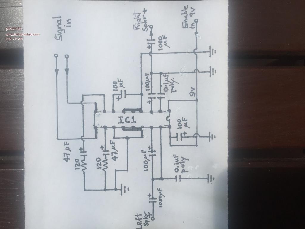 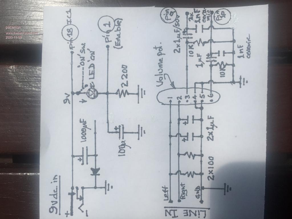 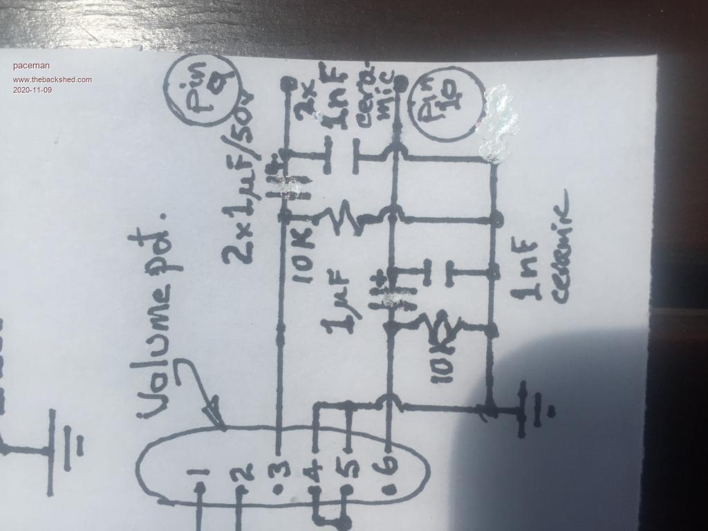 My "fix" of the garbling problem was to put a 1uF SMD cap in-line in both audio channel cables, this fixes the garbling but also limits the bass. Given that there are now two blocking caps in each channel's input, is there a better way of doing this? Also is the orientation of the amp's blocking cap back to front? Is someone able to shed some light on the identification of the amp IC. Greg |
||||
| TassyJim Guru Joined: 07/08/2011 Location: AustraliaPosts: 6538 |
The CMM2 likes the load to be 5k or greater. Your circuit shows 100 ohm resistors across the inputs. That is what I would expect if it's intended to be fed from headphone or speaker outputs, not line level. If the 100 ohm is correct, that would explain why 1uF results in loss of bass. It would also explain the distortion. A 4.7K resistor instead of the blocking capacitor would take the load off the CMM2 and might still give reasonable audio level. Jim VK7JH MMedit |
||||
| paceman Guru Joined: 07/10/2011 Location: AustraliaPosts: 1329 |
Hi Jim, thanks for looking at that. I guess that would also explain why they sound OK when fed direct from the notebook headphone output, certainly my headphones connected to that output sound good too. I'll give your 4.7K resistor suggestion a try. A dumb question coming up, but I assume you mean to put the 4.7's in-line in the cable, i.e. current limiting, not across to ground. Greg |
||||
| Volhout Guru Joined: 05/03/2018 Location: NetherlandsPosts: 5931 |
If an amplifier has a capacitor at the input, and it is a polarized capacitor (electrolytic, or tantalum) there is a chance that connecting the CMM2 causes a reverse polarity on that capactor. In that case the polarized capacitor can cause distortion, or start conducting. Volhout P.S. Geoff/Peter maybe next time ... add capacitors to the CMM2 at the audio output, and provide a bypass jumper for DC coupling for the 1 or 2 that use the DAC output for something else. PicomiteVGA PETSCII ROBOTS |
||||
| TassyJim Guru Joined: 07/08/2011 Location: AustraliaPosts: 6538 |
Yes, in series. VK7JH MMedit |
||||
| TassyJim Guru Joined: 07/08/2011 Location: AustraliaPosts: 6538 |
I decided to do a few experiments with different loading on the audio output. R1 is the series resistor and R2 is a shunt to ground. R2 goes via a 22uF capacitor to remove any DC effects. 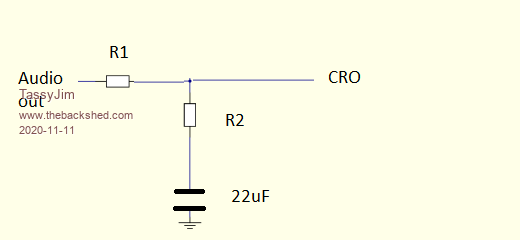 Initially I started with R1 = 0 ohms (shorted) and R2 = 4.7k 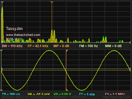 Next R2 = 1.8k - no obvious problems. 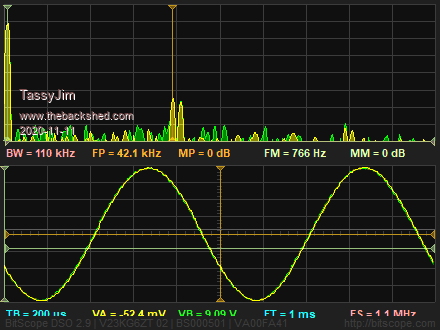 With R2 = 1k, flattening of the waveform is hard to see but the harmonics in the spectrum are growing. 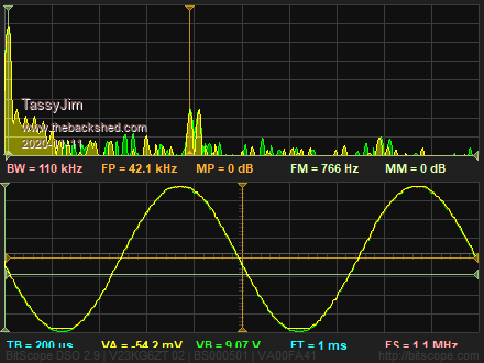 R2 390 ohms and the curve looks very flat. 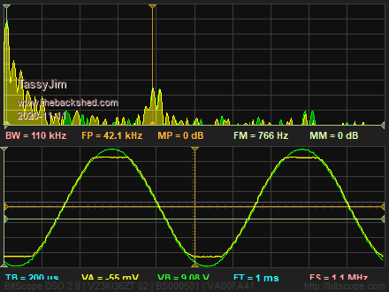 200 ohms and things look very bad. Even my cloth ears wouldn't like it. 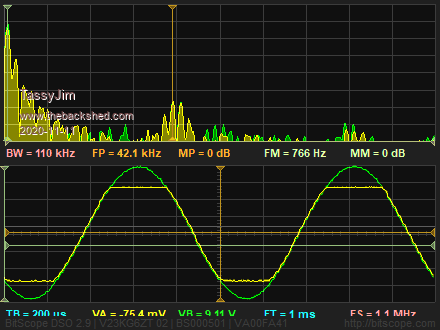 Connecting my speakers instead of the dummy loads and you can see one side flattening. It is one sided because there is no DC blocking capacitor. 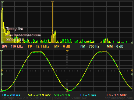 With my speakers, I found that 4.7k in series (R1) and 0.01uF shunting to ground gives a bit of low pass filtering and stops the over-loading of the audio output. Most of the audio problems so far can be put down to using amps with low input impedance. A 4.7k resistor in series with the audio output will resolve the distortion and still leave plenty of signal to disturb the neighbours. The data sheet calls for 5k or higher and I guess that they know what they are talking about. Jim Edited 2020-11-11 16:46 by TassyJim VK7JH MMedit |
||||
| paceman Guru Joined: 07/10/2011 Location: AustraliaPosts: 1329 |
Hi Jim and Volhout, Sorry to be a bit slow getting back but I've just got back from an unscheduled day/night stay in hospital - all OK again, I think. Again, thanks for expanding on the audio "thing". I'll have a good look at your plots tomorrow Jim and try the 4.7K series resistor. Will report back. Greg |
||||
| paceman Guru Joined: 07/10/2011 Location: AustraliaPosts: 1329 |
Hi Jim Yes, sure enough your 4.7K in series suggestion instead of the "external" blocking caps did the trick admirably. Bass is now perfectly reasonable (for little speakers, mid/upper range is quite good and there doesn't seem to be any obvious distortion. Problem solved. Needed a bit more volume pot but nothing too serious. Volhout's suggestion of adding jumperable 4.7's in the audio out lines of new PCB's sounds like a good idea given that the DAC outs will probably be used more for audio than voltage. Maybe jumperable pads so that individuals can choose the best resistance for their system. A note about it in the User Manual would also be a good idea. Greg |
||||
| TassyJim Guru Joined: 07/08/2011 Location: AustraliaPosts: 6538 |
I'm glad ts working for you. The manual does already suggest that the output is 'line level' and overloading is not desirable. It is under "Hardware features". Perhaps it should be repeated under "Audio Output" as well. Jim VK7JH MMedit |
||||
| Page 1 of 2 |
|||||
| The Back Shed's forum code is written, and hosted, in Australia. | © JAQ Software 2026 |
