
|
|
Forum Index : Microcontroller and PC projects : Questions, observations about Armmite F4 audio & amp modules
| Page 1 of 2 |
|||||
| Author | Message | ||||
| lizby Guru Joined: 17/05/2016 Location: United StatesPosts: 3782 |
For these tests I'm using Dollar Store ear phones, which cost $4 Canadian and are surprisingly adequate. I've tried a number of Aliexpress amplifier modules with differing results. (I understand that PLAY VOLUME L,R works for volume control.) 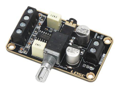 1) As I noted before, with this 5W amp , powered from F4 5V, it reboots the F4 if powered on, or if the volume is turned up too far, but plays ok if turned on at a low setting and volume control on the module works in a low range. This is two-channel.  2) With this two-channel PAM8406 amp, power on (3V3) and off works, audio is good from just a nudge above on through about a fifth of the nob turn range (about as loud as I'd want it anyway). Above that, it starts to sputter. This is the best fit of the ones I've tried. 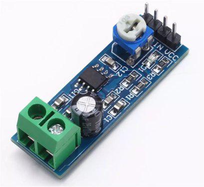 3) This is a single-channel amp, and works ok with the pot turned up about 9/10ths of the way clockwise (3V3 power). Within a narrow range, the pot controls volume, but outside that range the sound is either off or very noisy. Of these, #2 works best, but needs to have a mini-stereo socket added. I've also ordered some of these, also PAM8406-based--needs mini-stereo socket but perhaps better layout for F4 add-on with F4 volume control. If anyone has experience with other F4 audio output modules or circuits, please share. PicoMite, Armmite F4, SensorKits, MMBasic Hardware, Games, etc. on FOTS |
||||
TassyJim Guru Joined: 07/08/2011 Location: AustraliaPosts: 6538 |
I expect that you are over-driving the amp. From the datasheet for the PAM8406 How are you powering the modules or are you taking power from the F4? Without seeing the circuit for the modules and your interface, it is hard to comment further. Jim VK7JH MMedit |
||||
| lizby Guru Joined: 17/05/2016 Location: United StatesPosts: 3782 |
I'm not dissatisfied with the performance of the 2nd PAM8403 (I mislabeled it as a PAM8406). First module was powered with 5V from the F4 (I didn't try it, but after trying the other PAM8403 I'm guessing it would work with 3V3). The other 2 were powered with 3V3 from the F4. Inputs to all three modules were direct from the F4 DAC pins, 29 & 30 (PA4 & PA5) (or with the LM386 amp, first one DAC output and then the other). With volume control on the F4, there's no need for it on the amp module. I was just noting where in the pot range the sound was OK. I'm sure at the high end it was being overdriven--and the 5W module was way overkill for the headphones and, without a separate power supply, for the F4. I was somewhat surprised that the pot range was so narrow on the LM386 single-channel module--but I know nothing about amps and the analog circuitry for them in general. I had wondered what the minimum circuit was to get acceptable headphone music (and my attempt at Volhout's circuit failed, so I don't know about that), but at $.75 plus shipping of $1.29 Canadian for the PAM8403 with pot ($.45 without), it doesn't seem worth it to add components to my PCB. ~ Edited 2021-03-29 09:43 by lizby PicoMite, Armmite F4, SensorKits, MMBasic Hardware, Games, etc. on FOTS |
||||
| TassyJim Guru Joined: 07/08/2011 Location: AustraliaPosts: 6538 |
I will admit I am a long way out of date with my headphone knowledge but I thought they all would have a common ground for left and right channels. The PAM8406/3 are differential outputs so you can't just tie the -ve outputs together. The LM386 is more my vintage. Jim VK7JH MMedit |
||||
| matherp Guru Joined: 11/12/2012 Location: United KingdomPosts: 11498 |
Let's think about the basics. The output of the Dac's on the CMM2 and ArmmiteF4 swing between 0 and 3.3V (actually about 0.2 and 3.1V) An amplifier powered by 3.3V can swing between 0 and 3.3V if capable of perfect rail to rail operation. In other words you don't need an "amplifier". What you actually need is a unity gain buffer. For headphone use I would use a BUF634. For more power some sort of emitter follower could work. Any sort of gain at 3.3V supply is counterproductive. For a decent amplification use a 12V supply and then there are any number of cheap modules out there that work superbly |
||||
| lizby Guru Joined: 17/05/2016 Location: United StatesPosts: 3782 |
Exactly what I need. Ok. I'll order some. Meanwhile, I have some LM833N DIP8 dual audio op amps--can that be configured for unity gain? And would it be suitable for headphone use? (Any analog circuit designers available?) What about a "unity gain" emitter follower (or a pair of them)? I'm fumbling in the dark here. Any assistance from the more enlightened will be appreciated. Please assume complete beginner for this stuff PicoMite, Armmite F4, SensorKits, MMBasic Hardware, Games, etc. on FOTS |
||||
| matherp Guru Joined: 11/12/2012 Location: United KingdomPosts: 11498 |
I suspect not. Opamps that are unity gain stable normally say so explicitly in the datasheet Another good chip for a headphone amp is the LME49600 Edited 2021-03-29 22:26 by matherp |
||||
| Volhout Guru Joined: 05/03/2018 Location: NetherlandsPosts: 5926 |
Absolutely not. Not even close. The LM833 opamp when driven from +/- 15V can supply +/-10V in a 2kohm load. That is 5V voltage drop at 5mA load. A headset (even a high impedance one is 600 ohm, most are 32 ohm) will be to high load for this opamp. And you still would need to supply it with +/- 10V minimum to have any use. You should be looking for a 5V powered rail-rail opamp that can supply at least 30mA or so (for 1V over 32 ohm) for a practical implementation in an F4 setup. Configure the opamp for unity gain, add 0.7V offset (to make the output swing nicely in the 5V output window) through a bias resistor and capacitively couple the headset (100uF will be a good value electrolytic). The LME49600 is a good unity gain buffer, but it has some limitations. Under load the output voltage cannot reach rail to rail. In a typical headphone, and 0V-3.3V input levels you need to power it with minimum 3.3V+2V+2.5V = 7.8V (more than the 5V from USB). If that voltage is available (i.e. 9V/12V) then it is a good solution (add a capacitor from the output to the headphone, because this beast can deliver serious current (0.5 Amps !!). Plugging the headphone in (3.5mm jack) shorts the pins during plugin. 0.5A shorts are quite nasty. For 5V maybe look at something like the LM4992 (in a larger package, the WSON14 package is hard to solder). Look for Cell Phone audio amplifiers. For mono you can use the LM4862 (or 2 for stereo). Edited 2021-03-30 00:57 by Volhout PicomiteVGA PETSCII ROBOTS |
||||
| lizby Guru Joined: 17/05/2016 Location: United StatesPosts: 3782 |
Ok. Thanks very much for the good info. In conclusion, for me, no reason not to be happy with the PAM8403 module with volume control used to find the sweet spot on the headphones. For $2.04 Canadian (and it's working with 3V3 from the F4), how wrong can I go? I'll try the pot-less PAM8403 when it arrives, but without adjustment it might not be in that sweet spot. PicoMite, Armmite F4, SensorKits, MMBasic Hardware, Games, etc. on FOTS |
||||
| TassyJim Guru Joined: 07/08/2011 Location: AustraliaPosts: 6538 |
Unless your headphones have separate ground returns, you should NOT use the PAM8403 modules. You will be shorting the 2 channels together which is OK for true mono but can be a disaster when the right and left are different. The LM386 module you refer too looks the same as one I have used on a few occasions. As delivered they have a gain of 200 but that can be reduced to 20 by removing R1, the zero ohm resistor. For the F4, I would put a ~10k in series with a ~0.47uF capacitor in the input and run it of 9-12V. The minimum for the LM386 is 4V but 9 is much better. The series resistor in conjunction with the 10k pot will allow you to bring the overall gain to between 1 and 2 which will be about right for ear busting levels. Jim VK7JH MMedit |
||||
| Volhout Guru Joined: 05/03/2018 Location: NetherlandsPosts: 5926 |
For those who like breadboarding, this is a class A buffer for headphones that should work fine with the F4. 6 discrete components per channel (12 for stereo). It drives a 32 ohm headphone to max 3Vpp. A stereo pair of these buffers draws 90mA from 5V. The transistors can be any generic PNP (i.e. BC558, 2N3906). 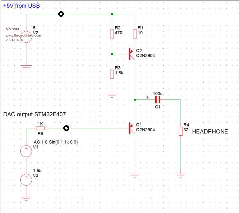 Edited 2021-03-30 18:27 by Volhout PicomiteVGA PETSCII ROBOTS |
||||
| lizby Guru Joined: 17/05/2016 Location: United StatesPosts: 3782 |
Thank you for that. What does the part of the circuit above the junction to the 100u cap do? Also, what is the meaning of V1, V2, and V3? PicoMite, Armmite F4, SensorKits, MMBasic Hardware, Games, etc. on FOTS |
||||
| Volhout Guru Joined: 05/03/2018 Location: NetherlandsPosts: 5926 |
Hi Lizby, In my profession as hardware engineer I tend to design electronics circuits in computer simulation using component models, and basic building blocks. The schematics shown above is the simulation model. This simulator does not know an STM32F407, therefore I replace the F407 analog (DAC) output with voltage sources. These are theoretical models, without practical limitations (so a 5V source (V2 above) can deliver 100000 A without voltage drop). V1 generates a sine wave 1Vrms (2.8Vpp) around 0. To bring this in line with the actual DAC output, and offset of 1.65V (half of 3.3V) is added by V3. R1 simulates the DAC output resistance inside the F407. The buffer is a very simple emitter follower (Q1) using a PNP transistor to bring the DC level from 0V...3.3V to 0.7V...4.0V (around the center of 5V, to avoid clipping). Since there is no feedback path in this amplifier/buffer distortion depends on the linearity of Q1. The upper part of the circuit (Q2, R1,2,3) is a simple (~40mA) current source. By keeping the current through Q1 as constant as possible, linearity is best. I also designed this amplifier for my own use. I need it for my handheld Tetris game based on an F4. The 40mA is much current for a handheld device, but so is LCD backlight. My Tetris sound is mono, so I only need a single buffer. Volume control is done using the software volume control in MMBasic. Edited 2021-03-30 22:05 by Volhout PicomiteVGA PETSCII ROBOTS |
||||
| lizby Guru Joined: 17/05/2016 Location: United StatesPosts: 3782 |
Volhout--thanks very much for the explanation. So much to learn about this stuff. PicoMite, Armmite F4, SensorKits, MMBasic Hardware, Games, etc. on FOTS |
||||
| lizby Guru Joined: 17/05/2016 Location: United StatesPosts: 3782 |
Here's another module which does a very good job for mono audio output from an F4 DAC with 3V3 power from the F4. 5128 Mono Audio Amplifier Module, 5W Class D  The music is audible on the headphones with PLAY VOLUME 2,2, and quite loud with PLAY VOLUME 25,25. ~ Edited 2021-03-30 23:52 by lizby PicoMite, Armmite F4, SensorKits, MMBasic Hardware, Games, etc. on FOTS |
||||
| Volhout Guru Joined: 05/03/2018 Location: NetherlandsPosts: 5926 |
For those who want to breadboard the circuit I provided 5 posts earlier, I have an update. The circuit is build, and tested, resulting in a few minor changes. 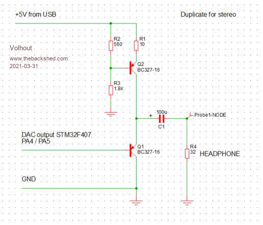 1 resistor value is changed, to ensure 40mA current. The transistors are BC327 or 2N4402 parts (have higher gain at 50mA) to improve linearity. I have made one observation, testing with different computers. On a 2021 laptop (Lenovo Thinkpad with i9 processor) running W10 there is a lot of noise in the audio. On a 10 year old HP Probook 4510, the audio is clean, almost no noise. For diagnosis I tried powering the amplifier from the F4 3.3V on the Lenovo (from a linear regulator), but the noise remained. Tonight I will check with a scope if this is from the 5V from USB, or if it is something in the F4 board. Additionally I will try to find out what the best audio format (quality wise) is what the F4 can produce (matherp ?) and encode some CD music in that format, to test the audio quality. The build configuration (veroboard): 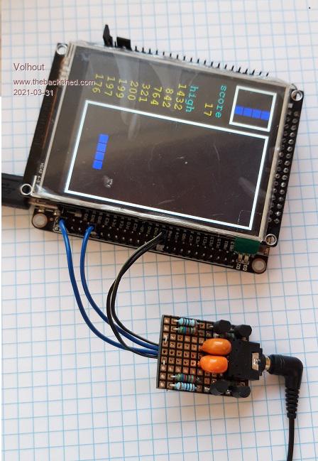 About volume settings: I can confirm that on VOLUME 100,100 the audio will deafen you on the pair of earplugs I am using. VOLUME 10,10 is better suited for intense listening. If you need background audio, VOLUME 3,3 is better. And that is why the noise on the Lenovo laptop is annoying. So the saga continues.... .. Edited 2021-03-31 16:56 by Volhout PicomiteVGA PETSCII ROBOTS |
||||
| phil99 Guru Joined: 11/02/2018 Location: AustraliaPosts: 3289 |
Extra low pass filtering on the input and 5V supply may help with the noise a bit, however much of it could be on the ground return. The usual cure for this is to take your ground wire directly to the analogue ground ref. pin on the processor. I think this is pin 20, though the junction of C23, c24 & R35 would be easier to solder to. If that is too difficult add a 10 to 33 ohm resistor between supply ground and your decoupling capacitor. 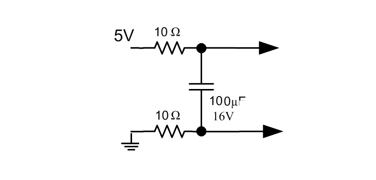 |
||||
| matherp Guru Joined: 11/12/2012 Location: United KingdomPosts: 11498 |
It is much better to use an analog volume control. The digital volume effectively just loses resolution i. 12-bit DAC becomes 11-bit DAC at 50% volume Both FLAC and WAV will use the full 12-bits so either should give the best sound output |
||||
| lizby Guru Joined: 17/05/2016 Location: United StatesPosts: 3782 |
Is this saying that it's better to have pot-adjusted volume control (as with the Mini PAM8403 shown above) than to use PLAY VOLUME L,R? What about fitting the output of the DAC to the range of the pot (with that PAM8403 module, only the lower fifth of the knob range can be used before it becomes too loud for the headphones--or does that depend on what you're driving, e.g., headphones, small speakers, sound system). PicoMite, Armmite F4, SensorKits, MMBasic Hardware, Games, etc. on FOTS |
||||
| matherp Guru Joined: 11/12/2012 Location: United KingdomPosts: 11498 |
Yes The issue is that your amplifier has too much gain as discussed above. You can add extra resistance at the +ve end of the pot to create a voltage divider. This may decrease the S/N ratio slightly but better than using the digital volume |
||||
| Page 1 of 2 |
|||||
| The Back Shed's forum code is written, and hosted, in Australia. | © JAQ Software 2026 |
