
|
|
Forum Index : Microcontroller and PC projects : PicoMite VGA Edition - pcbs etc.
| Page 1 of 3 |
|||||
| Author | Message | ||||
| Mixtel90 Guru Joined: 05/10/2019 Location: United KingdomPosts: 8904 |
Provisional pic of pcb to fit the 90x70x28 case. I've put a RTC on I2C2 and a SDcard on SPI. RTC pullups can be omitted but I put them in just in case someone wanted to use the I2C without a RTC. The 2-wqy and 4-way headers at the top allow a piece of strip or padboard to be added, running all along the top of the board if required. The 2-pin carries 5V/GND and the 4-pin has 3v3,GND and 2 spare pins for stability. There are positions for a 3v Vref diode and a 5v input series diode if required. Once again, 5v input is via a 3.5mm/1.3mm barrel jack. I'm intending to try something different this time and notch the board myself to get the end panels included without paying extra. The idea is to use a 30 degree carbide V cutter in a dremel and use some sort of straight edge as a guide. We'll see if it works. :) 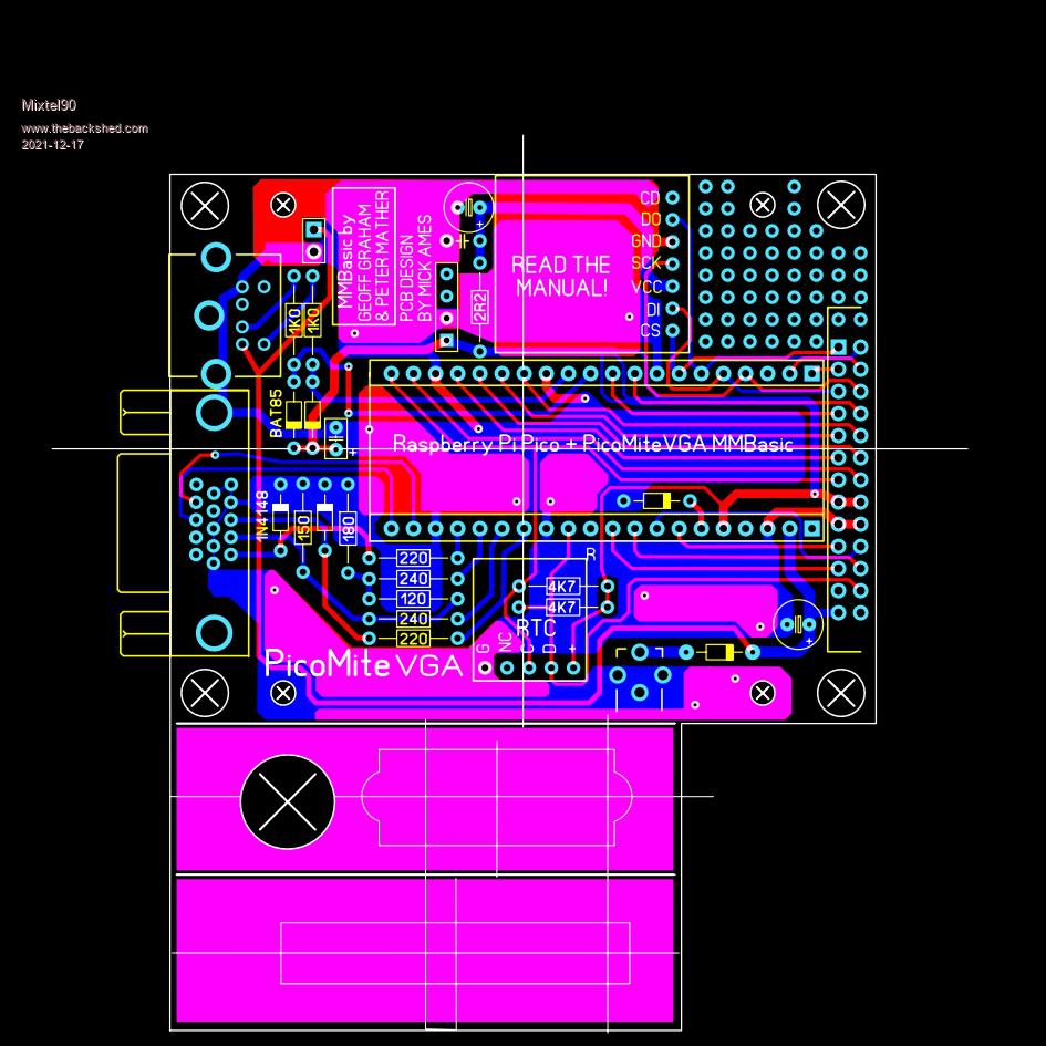 Edited 2021-12-17 08:15 by Mixtel90 Mick Zilog Inside! nascom.info for Nascom & Gemini Preliminary MMBasic docs & my PCB designs |
||||
| phil99 Guru Joined: 11/02/2018 Location: AustraliaPosts: 3289 |
Very nice. For the few keyboards that don't have their own pullups they can be put across the two BAT85 protection diodes. 10k should work. |
||||
| robert.rozee Guru Joined: 31/12/2012 Location: New ZealandPosts: 2528 |
perhaps a silly question - will the pico sit high enough that you can still plug into the USB socket to upgrade firmware? none of the layouts put forward appear to have the pico orientated so it's 2 rows of pins are parallel to the 40-pin connector. if pins were wired 1-1 (are we doing this?) then that would lead to a far more compact layout. cheers, rob :-) |
||||
| Mixtel90 Guru Joined: 05/10/2019 Location: United KingdomPosts: 8904 |
phil: I'm still playing. I had pullups on there at one point but then decided to use series resistors & clamp diodes - forgetting to put them back. :) I'll have another look round that area. rob: It does, just about, but not while in the case because the end panel blocks it off. This is one of the things I'm still sorting out - the mechanics of actually getting the thing into the case. If there's enough space over the IO connector I'll put a hole for a USB plug, if not then I won't. The barrel jack only needs a notch in the top and botom of the case. The SDcard, if the socket is spaced up by 1.6mm, can also be done with a notch in theory. I don't want to drill the sides of the case as it makes things difficult, which brings me nicely to USB socket access... I used the parallel layout when I did my backpack PCB and it works well. However, in this case I already had a well advanced drawing for the Black Pill to work from so I've been carving that up. The parallel layout is great until you want to get pins out through the other side, then they always seem to end up in exactly the wrong places. lol. e.g. in this case PS/2 is on the opposite side to VGA and there are insufficient pins on the VGA side for an SDcard unless you lose the analogue pins. I always like to run the analogues together too, away from digital noise if possible. On PS/2 input protection: In simulation, series resistors of 270R are needed to pull 10k pullups down to 0.5v, remembering that PS/2 is bi-directional. The BAT85 is a small signal schottky type and has a very low Vf at low currents. There's only about 300uA of input current to be sunk in total and the input is, in theory anyway, at less than 3.5v which is nicely within the 3.6v continuous limit - and the current is limited to 150uA anyway. This may not give full protection if a device is connected that forces 5V into the PS/2 as the input will go up to 3.8v, but this shouldn't happen. My only reservation is that there are some PS/2 mice that are not oc output and someone will probably try one eventually. Incidentally, I originally had a link to select 3.3v or 5v for the keyboard. However, I checked on keyboard current consumption and the PS/2 spec allows over 250mA for a keyboard. The one I have connected to the CMM2 is 100mA. In view of that, and the fact that the PicoMite SMPS gets noisier with increasing load, I decided to keep the keyboard at 5v. Edited 2021-12-17 18:30 by Mixtel90 Mick Zilog Inside! nascom.info for Nascom & Gemini Preliminary MMBasic docs & my PCB designs |
||||
| Mixtel90 Guru Joined: 05/10/2019 Location: United KingdomPosts: 8904 |
Version a02 VGA sorted out in line with Peter's correction. PS/2 pullups added & series resistors reduced (after simulation). VREF diode moved & now on AGND to reduce noise. Additional GND added next to 5v pin. Some general tidying up. Wondering if it's worth squeezing in the bits for a (SMD) linear voltage reg... What shall I use the spare IO pin for? You never actually *finish* a pcb design, do you? You just send it for manufacture. :) Hopefully I'll be able to sort out the mechanical side shortly and correct the cutouts in the end panels. 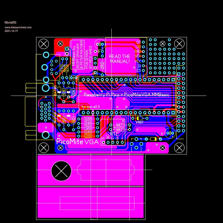 Mick Zilog Inside! nascom.info for Nascom & Gemini Preliminary MMBasic docs & my PCB designs |
||||
| vegipete Guru Joined: 29/01/2013 Location: CanadaPosts: 1179 |
The SD card is on a little pcb with through hole mounting pins. Any chance of mounting it so that access is above or below the 26 pin header? Order of assembly starts to matter as the SD board would block access to the header pins on the bottom, but that is minor. Visit Vegipete's *Mite Library for cool programs. |
||||
| Mixtel90 Guru Joined: 05/10/2019 Location: United KingdomPosts: 8904 |
It's a microSD socket that's at right-angles to the row of pins on its PCB. Like this. There's actually a gap between the bottom of the uSD module and the pcb. I'm not intending to make it plug-in so it's closer to the pcb than the PicoMite. It can't really go above the header because of support problems (the pins would be long). Beneath the header might be possible, but I lose the access width to the sea of holes, which I'd like to keep really as the user could possibly fit a jack socket or something there. I'm currently trying to figure out how stuff fits on the CAD. SL6 isn't very good for that. EDIT: Just tried it. If I put the uSD module on the back of the pcb it won't line up with the end cover. I don't *think* it will fit over the top of the IO socket either. There's not much room to work in these boxes. :( Edited 2021-12-18 05:58 by Mixtel90 Mick Zilog Inside! nascom.info for Nascom & Gemini Preliminary MMBasic docs & my PCB designs |
||||
| vegipete Guru Joined: 29/01/2013 Location: CanadaPosts: 1179 |
Why does that item claim to be a "Level Shifting Micro SD Board Breakout Module For 3.0V to 5.0V"? Are there components on the bottom? Visit Vegipete's *Mite Library for cool programs. |
||||
Grogster Admin Group Joined: 31/12/2012 Location: New ZealandPosts: 9975 |
Mick: When you have finished this design, are you going to make the files available? I was going to start designing a board for it, but you have essentially already completed one, so there is little point in my re-inventing the wheel!  I also use SL6, so I would be most interested in the LAY6 file. EDIT: BTW, I have a large collection of macros I designed for various things in SL6. Would you like a copy of these? Edited 2021-12-18 14:51 by Grogster Smoke makes things work. When the smoke gets out, it stops! |
||||
| Mixtel90 Guru Joined: 05/10/2019 Location: United KingdomPosts: 8904 |
The advert seems to tell lies, vegipete. :) I have two of these and they don't seem to do any level shifting at all. They work nicely with a PicoMite and the design works well for mounting on stripboard. It's not actually a good solution to the problem in this case and it'll be difficult/almost impossible to access the uSD. There's a 0.5mm air gap and 2mm of case wall, and the uSD is a click-click type that is within the area of its pcb. I'd rather have used a standard size card but the case size makes that *very* difficult. Eventually I figured that I was essentially doing this for myself I didn't mind as the chances of the card being removed are actually pretty slim and I don't mind opening the case if necessary. I'm intending that the end panels will give ample support for the pcb and just a couple of fixing screws to hold the case together will suffice. Oh yes, Grogster, but it's not quite ready for Gerbers yet. I'd like to at least sort out the end panels first. I thought it was straightforward at first, but it's not, of course. lol Your macros would definitely be of interest, thanks very much. :) lay6 file: PicoMiteVGA.zip This is very much "work in progress" and will no doubt change in several ways today. :) Mick Zilog Inside! nascom.info for Nascom & Gemini Preliminary MMBasic docs & my PCB designs |
||||
| matherp Guru Joined: 11/12/2012 Location: United KingdomPosts: 11499 |
Mick Have you seen this sdcard breakout? |
||||
| Mixtel90 Guru Joined: 05/10/2019 Location: United KingdomPosts: 8904 |
No, I hadn't. Thanks. It's a bit bigger than the one I'm looking at at the moment and wouldn't fit in the same place. However, the card might be in a very slightly better position. I've been playing on the CAD. I can't find a better alternative position, unfortunately. Not without soldering a SMD socket to the board anyway. However, even with access from the side there isn't much plastic work to create card access. I've discovered that there's no need to pack the header up by 1.6mm either so that makes things a bit easier. :) Mick Zilog Inside! nascom.info for Nascom & Gemini Preliminary MMBasic docs & my PCB designs |
||||
| Grogster Admin Group Joined: 31/12/2012 Location: New ZealandPosts: 9975 |
Looking good so far.  Here are my macros. There are 343 macros in this zip. They were all designed to cater for things that were not in the standard macros. I keep them in a separate folder under MACROS, so that they don't get mixed up with the standard ones that come with the SL6 install. MACROS(Graeme's).zip Smoke makes things work. When the smoke gets out, it stops! |
||||
| vegipete Guru Joined: 29/01/2013 Location: CanadaPosts: 1179 |
Is there a particular pinout for the 26 pin header? Is it matching something else? Visit Vegipete's *Mite Library for cool programs. |
||||
Cyber Senior Member Joined: 13/01/2019 Location: UkrainePosts: 161 |
I see there is much hurdle to cram in so many onto so little board. May be it's better to choose bigger case and use larger PCB? |
||||
| Mixtel90 Guru Joined: 05/10/2019 Location: United KingdomPosts: 8904 |
No, vegipete, it's not laid out like anything else. I just happened to have several 13+13 headers left over from the serial port on the (delayed) Nascom-4 project and one just fitted rather nicely. :) If I have to move anything around it might change. Oh, Cyber... I can't give up on this now! :) I'm sure you'd understand if you had one of these little boxes in your hands - they are a design challenge and I enjoy playing with CAD. lol The next size up, that is anything like easy to get, is probably the case used for the CMM2. I didn't find that easy to get *at a reasonable price* in the UK when I was building mine because I only wanted one. Remember too, that PCBs at 100mm square are pretty cheap. Above that they get more expensive, so your ideal would be a case to take a 100mm square pcb (or maybe a bit under). I can't find any at all. The pcb for this little case is (currently) 82mmx95mm including pre-cut & printed ends for the case so it's not all that far from ideal. I have an idea for using even more of the 100mmx100mm area too. Mick Zilog Inside! nascom.info for Nascom & Gemini Preliminary MMBasic docs & my PCB designs |
||||
| matherp Guru Joined: 11/12/2012 Location: United KingdomPosts: 11499 |
Mick Hammond 1593WBK is a nice case and widely available at sensible cost |
||||
| Mixtel90 Guru Joined: 05/10/2019 Location: United KingdomPosts: 8904 |
Oh, yes, that does look like a good one! I like the Hammond stuff - they give (usually) sensible drawings and CAD models to work from. Mick Zilog Inside! nascom.info for Nascom & Gemini Preliminary MMBasic docs & my PCB designs |
||||
| matherp Guru Joined: 11/12/2012 Location: United KingdomPosts: 11499 |
Here is my take on a PCB for the PicoMite VGA using the normal Maximite box VGAMite - Project.pdf The Pico protrudes to the back panel so the board can be powered by the Pico USB or alternatively you can use the 2.1mm jack (supply still must be 5V). The power is a full size TO220 linear low drop out regulator (TC1264-3.3) TYhe board has two slots for Pico Shields allowing for things like GPS or ESP8266. There are footprints for both the widely available DS3231 modules SDcard is the Adafruit 3V module so there are NO SMD COMPONENTS. I'm using a proper level shifter for the PS2 allowing the keyboard to work off 5V The green VGA signal uses a R2R DAC with 220R resistors (2 in parallel to give the one 110R needed). There is then a trimmer to match the full green level with red and blue The 40-pin front panel connector uses a 1:1 pinout with the Picomite to keep things easy. All track widths and clearances are easily within the requirement for the cheapest PCB manufacture at JLC 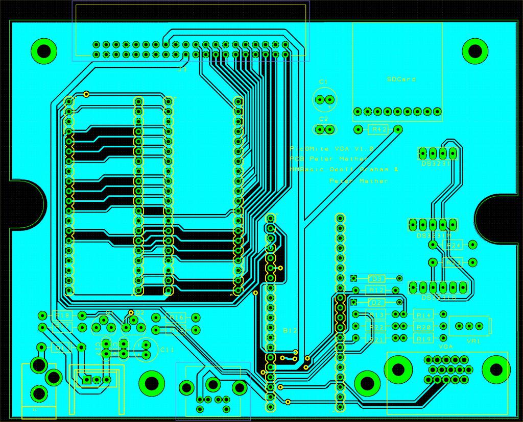 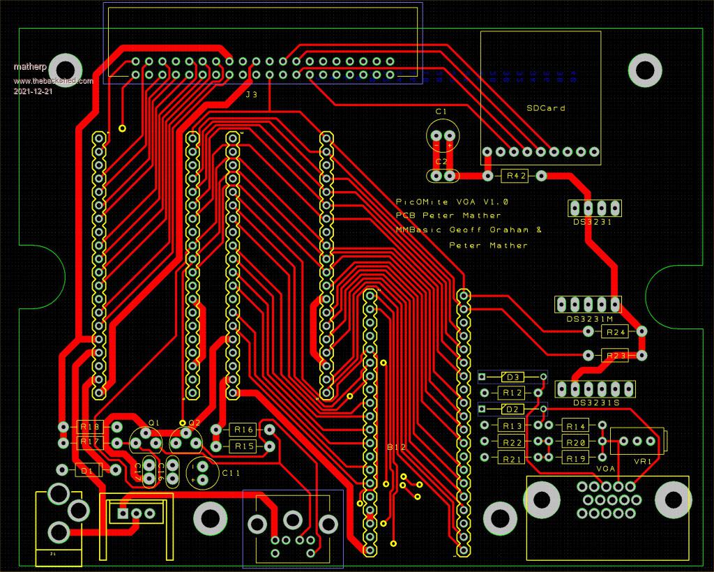 |
||||
| Mixtel90 Guru Joined: 05/10/2019 Location: United KingdomPosts: 8904 |
Nice! :) You must have been reading my mind. :) I added the option of using a linear voltage reg this morning before I went out, but mine is SMD and mounted underneath the PCB. It's general purpose, optional and connection is by links so it could be used to power a ESP8266-01S rather than use the PicoMite SMPS. 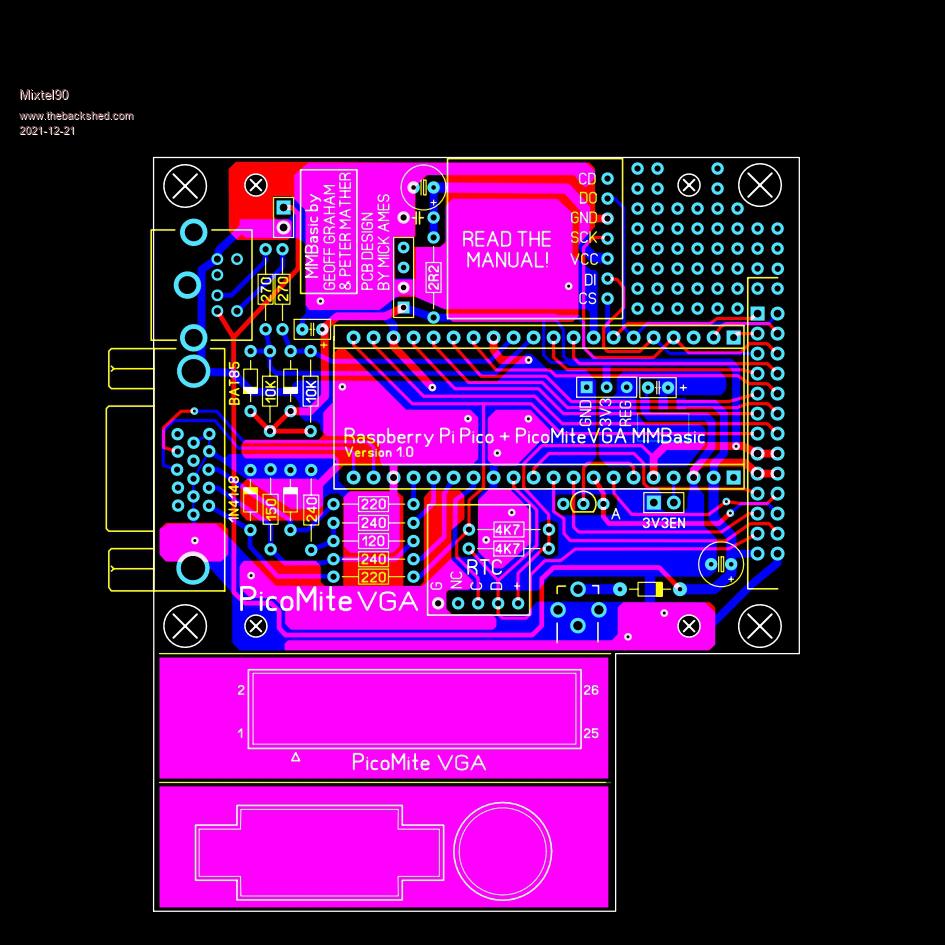 Now upped to version 1.0 as I don't think I'll take this much further unless I find a problem. Added Reset to the IO connector and changed VREF diode pads so it fits better. I've just tipped the SDcard capacitor on its side too, allowing easier component placement on the expansion board if it's used. Gerber files if anyone is interested: PicoMiteVGA10.zip Edited 2021-12-21 04:23 by Mixtel90 Mick Zilog Inside! nascom.info for Nascom & Gemini Preliminary MMBasic docs & my PCB designs |
||||
| Page 1 of 3 |
|||||
| The Back Shed's forum code is written, and hosted, in Australia. | © JAQ Software 2026 |
