
|
|
Forum Index : Microcontroller and PC projects : RS485 questions
| Page 1 of 2 |
|||||
| Author | Message | ||||
| lizby Guru Joined: 17/05/2016 Location: United StatesPosts: 3816 |
I have a Renogy Rover Elite solar charge controller which has an RJ45 jack labelled RS485. I've found a github site where someone has accessed the device with python: https://github.com/CyberRad/CoopSolar. That site also has a pdf for the device: https://github.com/CyberRad/CoopSolar/blob/master/ROVER_MODBUS.pdf. Good info. I have an RS485 module from aliexpress, https://www.aliexpress.com/item/1005003204223371.html, but I don't understand how it is supposed to be connected. The screw terminals are connected to A and B, but at the other end of the device, what are DI, DE, RE, and RO?  I was looking for an RS485 to serial module, but perhaps this isn't one. PicoMite, Armmite F4, SensorKits, MMBasic Hardware, Games, etc. on FOTS |
||||
TassyJim Guru Joined: 07/08/2011 Location: AustraliaPosts: 6548 |
The MAX485 data sheet gives you a clue. 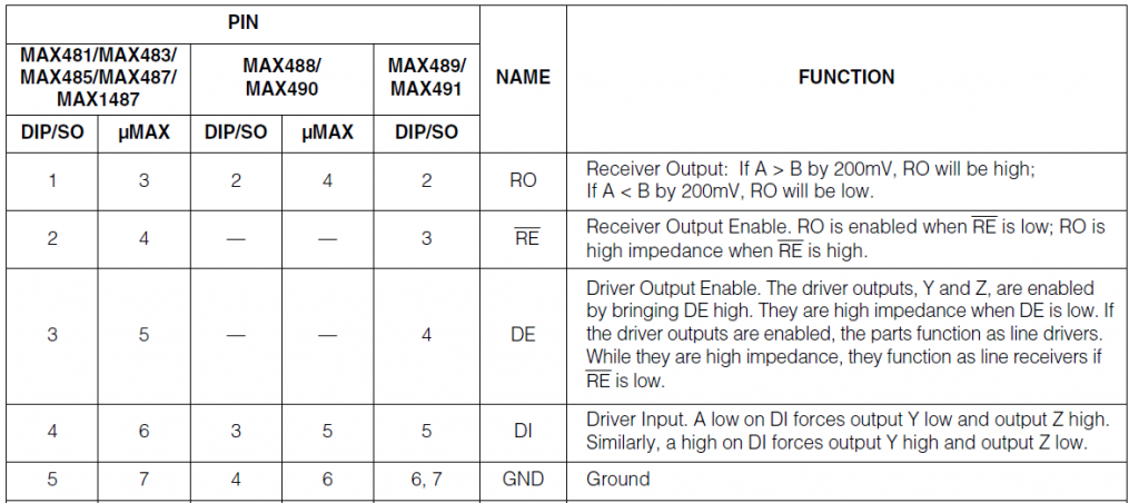 Jim VK7JH MMedit |
||||
| TassyJim Guru Joined: 07/08/2011 Location: AustraliaPosts: 6548 |
This is more like you want. It does the handshaking for you. https://www.aliexpress.com/item/1005001621746811.html Jim VK7JH MMedit |
||||
| Turbo46 Guru Joined: 24/12/2017 Location: AustraliaPosts: 1694 |
Yes. You have the right module see Mick's circuit . Note that DE and RE are normally connected together. Also that the DE provided by the Micromite (170) are inverted if you are using that but it's easy enough to roll your own DE signal. You will find MODBUS CRC routines on Fruit of the Shed. 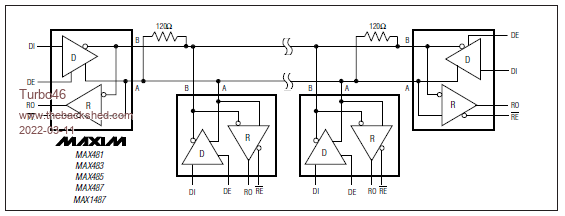 This circuit from the Maxim datasheet shows how to interconnect them. Note that the resistors from Mick's circuit are already fitted to your module. Bill Keep safe. Live long and prosper. |
||||
| lizby Guru Joined: 17/05/2016 Location: United StatesPosts: 3816 |
Bill--I already have RS485 coming out of the Renorgy device, so I don't need two modules which talk to each other. But thanks for explaining how the signals go. Jim--thanks for the link. I already ordered 5 of those from Amazon last night, and should have them tomorrow. Translating the python code looks fairly straightforward, if tedious. MMB4L on a PiZW or MMB on a pico with lcd and SD (I ask myself)--hmmm--better battery operation or wifi (or pico with ESP-01)? PicoMite, Armmite F4, SensorKits, MMBasic Hardware, Games, etc. on FOTS |
||||
| Mixtel90 Guru Joined: 05/10/2019 Location: United KingdomPosts: 8965 |
Just be careful with those modules, lizby. I see that they don't include a ground connection between the RS485 devices. They'll usually work with a 2-wire connection, but not reliably over any distance. You may have to add a ground connection somehow. Mick Zilog Inside! nascom.info for Nascom & Gemini Preliminary MMBasic docs & my PCB designs |
||||
| lizby Guru Joined: 17/05/2016 Location: United StatesPosts: 3816 |
Thanks for that, Mick. I wondered if the third large pad on the end might be ground--I'll check it. Distance will be very short--inches. PicoMite, Armmite F4, SensorKits, MMBasic Hardware, Games, etc. on FOTS |
||||
| Mixtel90 Guru Joined: 05/10/2019 Location: United KingdomPosts: 8965 |
You'll probably get away with it then. If you were sharing a power supply you'd have a common ground. Mick Zilog Inside! nascom.info for Nascom & Gemini Preliminary MMBasic docs & my PCB designs |
||||
| lizby Guru Joined: 17/05/2016 Location: United StatesPosts: 3816 |
The Renogy box is powered from the battery. I guess if the pico or pi is also, then they would indeed share a common ground. PicoMite, Armmite F4, SensorKits, MMBasic Hardware, Games, etc. on FOTS |
||||
| Mixtel90 Guru Joined: 05/10/2019 Location: United KingdomPosts: 8965 |
Just try it first. Over a short distance it might be fine. Just get A and B the right way round. :) The Pico isn't particularly battery-friendly (although it helps a lot if you can drop the CPU speed right down). Mick Zilog Inside! nascom.info for Nascom & Gemini Preliminary MMBasic docs & my PCB designs |
||||
| lizby Guru Joined: 17/05/2016 Location: United StatesPosts: 3816 |
This is a 12V 100Ahr LiFePO4 battery with solar charging, so I'm not too worried about what a picomite will draw, or even a PiZW. PicoMite, Armmite F4, SensorKits, MMBasic Hardware, Games, etc. on FOTS |
||||
| Mixtel90 Guru Joined: 05/10/2019 Location: United KingdomPosts: 8965 |
It probably won't notice the Pico much. lol Mick Zilog Inside! nascom.info for Nascom & Gemini Preliminary MMBasic docs & my PCB designs |
||||
| Turbo46 Guru Joined: 24/12/2017 Location: AustraliaPosts: 1694 |
For what it's worth, I believe this is the circuit diagram of that RS485 module. The four pins on the outside of the A and B screw terminals are the 5v, B, A and GND pins. 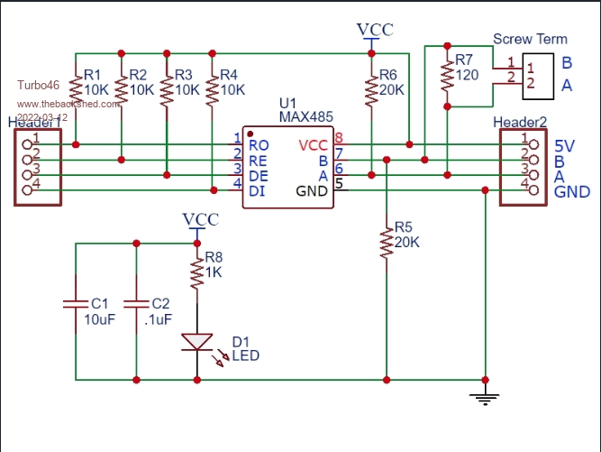 I have used the MAX485 at 3.3v so that should be OK for short distances at least. Bill Keep safe. Live long and prosper. |
||||
bigmik Guru Joined: 20/06/2011 Location: AustraliaPosts: 2981 |
Hi Mick (the other one), All, With my 33 years experience of 4 wire (nil of 2 wire) you do not need a GND wire between the 485 devices. In fact over distances it may impact on reliability. We drove 485/422 over distances of 1500m (roughly 1 mile) with no GND but the cable was shielded and GND Ed at the server end only. We, in later years of my work, used un shielded cat 5 over a few hundred metres, for temporary cabling. The cable we used for general permanent was actually 5pair (10 wires) plus shield and only CAT3 standard. We drove the 485 at 9600 baud so not sure what faster speeds it could carry over those distances on CAT3. RS485 is very robust and reliable, the signal does not rely on a GND reference as the principle is the differential voltage between the data+ and data- wires. If a spike occurs both wires will see the same spike but the differential would be the same as both will spike an almost identical amount in the same direction. A GND wire could cause complications as over the large distances the power sources would most certainly be from different switchboards and possibly phases.. Anyway rs485 is a lot of fun to play with. Regards, Mick Edited 2022-03-12 11:49 by bigmik Mick's uMite Stuff can be found >>> HERE (Kindly hosted by Dontronics) <<< |
||||
| Mixtel90 Guru Joined: 05/10/2019 Location: United KingdomPosts: 8965 |
I am enlightened, Mick. :) Just about all the documentation I've read regarding RS485 has said that, although unnecessary in some circumstances, the ground conductor is always recommended. Combined with the two balancing resistors at each end (or sometimes distributed over the network) it apparently helps keep the signal within the common mode range of the receivers and reduces errors. The mean of the common mode signal can, seemingly, drift with respect to GND, causing the limits of the signal to "bump" against the acceptable range of the receiver. I don't have your practical experience with long distance RS485 so I've nothing else to go on. There's nothing like actual installations to discover what's really needed - and I've seen some horror stories about RS485/RS422 gear that wouldn't talk to each other without all sorts of messing about with the topology! Perhaps the answer is to put the ground wire in - you don't *have* to connect it to the gear, just a decent earth point at one end. It would be a pig if you discovered that you needed it *after* wiring. :( At the end of the day it's the cable capacitance and speed that decide what you can do. :) Mick Zilog Inside! nascom.info for Nascom & Gemini Preliminary MMBasic docs & my PCB designs |
||||
| Turbo46 Guru Joined: 24/12/2017 Location: AustraliaPosts: 1694 |
Most important. In my working life we used MODBUS over RS485 in high voltage electricity substations. No problems within the switch house but now fibre optics are used to communicate with devices in the switchyard. Earth faults and lightening strikes can cause horrendous rises is the earth potential and cause untold damage. Lizby has none of those issues but if he has the need to interconnect the earths between the devices, I would use an external connection apart from the shielded and twisted pair cable that he uses (I hope) to connect the two devices. Perhaps a high wattage 100 - 1000 ohm resistor in series with the earth interconnection might be a good idea. The program is probably a greater problem. We never had any issues with communications. You just need the correct baud rate, A - A and B - B, shield connected at one end and away you go. Bill Keep safe. Live long and prosper. |
||||
| Turbo46 Guru Joined: 24/12/2017 Location: AustraliaPosts: 1694 |
You may find one of these USB to RS485 converters useful if you are doing any development on a PC. 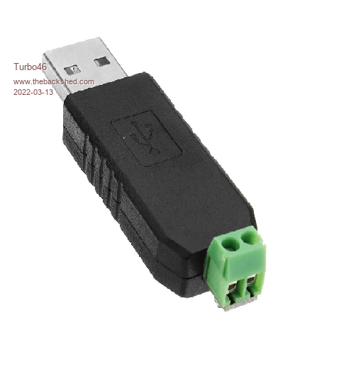 Automatic flow control, no ground connection but works well with an un-grounded device. Available at various places, there are other types with GND connection and more too. Bill Keep safe. Live long and prosper. |
||||
Grogster Admin Group Joined: 31/12/2012 Location: New ZealandPosts: 9996 |
I've just started to begin to play with RS485, so this thread is very interesting to me. @ Jim - the module you linked to with the automatic handshaking, do you know what the third connection is on the 485 side? We have A+ and B-, and a third terminal with Chinese symbols. Is that ground perhaps? Just curious. I will get a few of these to play with, as they are so cheap. Also, that listing says up to 128 devices on the one bus, but the RS485 standard says the maximum is "At least 32 unit loads", which is kinda vague... For what I am planning, I would need MORE then 30 nodes if possible. Around 50-ish would be perfect. Each node would be about 5-10 meters apart, but all daisy-chained back to the master controller. Is a module like that one full-duplex, or half-duplex? The fact it has TXD and RXD lines and LED's, kinda suggests that you can both transmit from the controller to the nodes, and the nodes can transmit back to the controller on the same two-wire bus. Do I have that correct or totally wrong? Perhaps I need four-wires and two modules - one is a transmit bus, the other is a receive bus? Sorry for the newbie questions, but I have HEARD of RS485, but I have never played with it, but it sounds perfect for the kinds of serial links that I currently use standard unbalanced UART for. Mick is obviously one of the 485 gurus here, so perhaps he will chime in also.  Smoke makes things work. When the smoke gets out, it stops! |
||||
| Turbo46 Guru Joined: 24/12/2017 Location: AustraliaPosts: 1694 |
Strictly half duplex Master and Slave communicate over the one pair of wires. The slave does not initiate communication - only the master the slave only answers when spoken to (like a good child - yeah right). The auto direction control in those devices is normally controlled by an RC network on the Tx line switching a Schmitt trigger. There is some delay in switching the direction at the start of the signal (message) and even more delay switching it off. So it is not really suitable for high speed communications and rapid responses. I have not done the maths but I would expect that 30 devices on one line would be a few too many. You could use several of the modules in parallel and split your slaves into several separate groups though. I can't find the circuit right now but if you want it I'll try later. I have a feeling that Mick (Mixtel90) may have had the circuit incorporated on one of his early boards. Bill Edit: Here 'tis 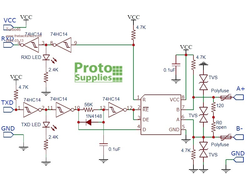 Edited 2022-03-13 18:18 by Turbo46 Keep safe. Live long and prosper. |
||||
| Mixtel90 Guru Joined: 05/10/2019 Location: United KingdomPosts: 8965 |
This is what I came up with eventually: 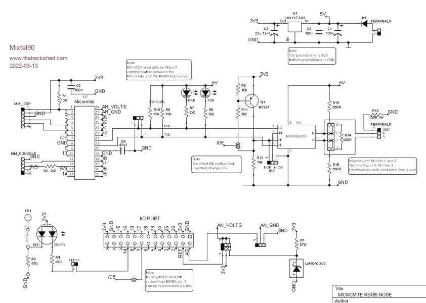 It looks intimidating, but I included inverted and non-inverting options for /EN and most possibilities of termination. :) Edited 2022-03-13 18:58 by Mixtel90 Mick Zilog Inside! nascom.info for Nascom & Gemini Preliminary MMBasic docs & my PCB designs |
||||
| Page 1 of 2 |
|||||
| The Back Shed's forum code is written, and hosted, in Australia. | © JAQ Software 2026 |
