
|
|
Forum Index : Microcontroller and PC projects : OPTION settings for Waveshare Pico displays sans MISO pins ?
| Page 1 of 2 |
|||||
| Author | Message | ||||
| hitsware2 Guru Joined: 03/08/2019 Location: United StatesPosts: 738 |
I.E. ST7789 or ST7735 controllers my site |
||||
| Rickard5 Guru Joined: 31/03/2022 Location: United StatesPosts: 463 |
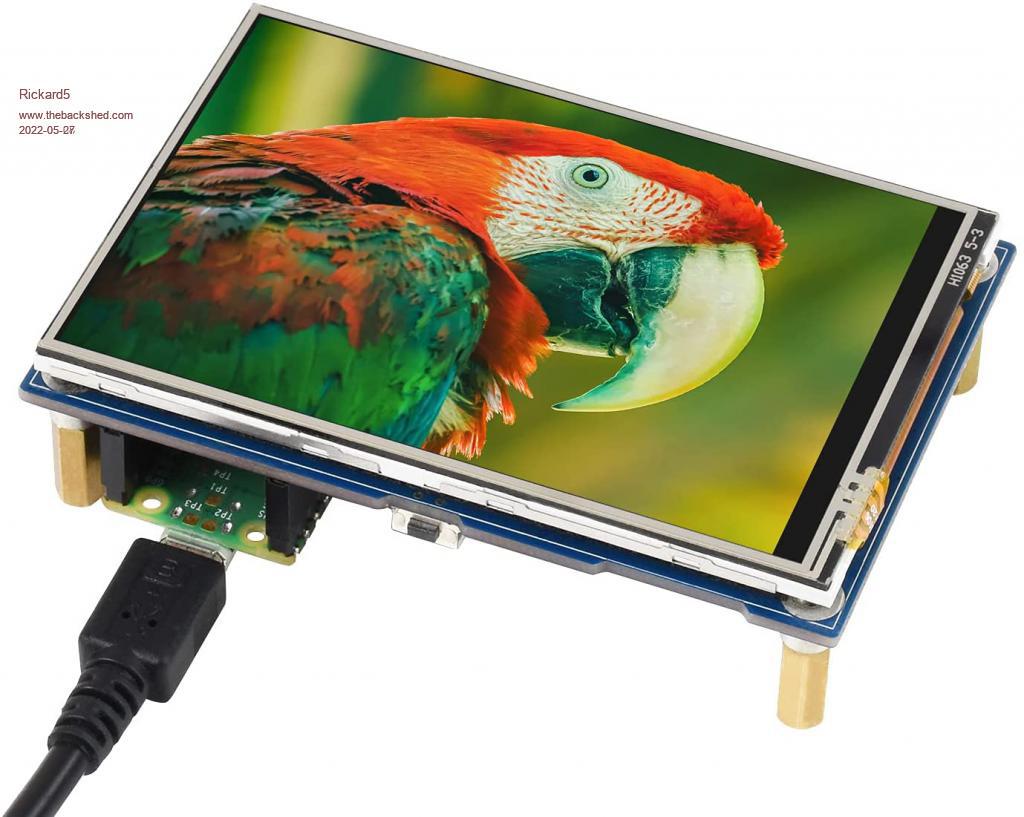 are you talking about this one with the Pico socket on the back? OPTION SYSTEM SPI GP10,GP11,GP12 OPTION LCDPANEL ILI9488W, LANDSCAPE,GP8,GP15,GP9,GP13 OPTION TOUCH GP16,GP17 GUI CALIBRATE 0, 3946, 211, -1287, 853 OPTION SDCARD GP221 I may be Vulgar, but , while I'm poor, I'm Industrious, Honest, and trustworthy! I Know my Place |
||||
| Mixtel90 Guru Joined: 05/10/2019 Location: United KingdomPosts: 8682 |
AFAIK you'll have to specify a MISO pin as the system expects it. You won't be able to connect it to anything, of course. Mick Zilog Inside! nascom.info for Nascom & Gemini Preliminary MMBasic docs & my PCB designs |
||||
| hitsware2 Guru Joined: 03/08/2019 Location: United StatesPosts: 738 |
> are you talking about this one with the Pico socket on the back? This One ..... my site |
||||
| hitsware2 Guru Joined: 03/08/2019 Location: United StatesPosts: 738 |
Get errors .... MMBasic expects it , but not the board ... my site |
||||
| Mixtel90 Guru Joined: 05/10/2019 Location: United KingdomPosts: 8682 |
The MISO signal is from the display to MMBasic. It is only used when MMBasic is trying to read from the display memory. That depends on which commands are being used. Without it you can't use BLIT, BLIT READ or transparent text. I'm not certain if the Touch commands work either. You may have to tie the MISO input to ground so that it doesn't get spurious information. if that worries you, do it via a resistor to protect the pin if it becomes an output. Mick Zilog Inside! nascom.info for Nascom & Gemini Preliminary MMBasic docs & my PCB designs |
||||
| hitsware2 Guru Joined: 03/08/2019 Location: United StatesPosts: 738 |
The MISO pin with this (these) controllers is " hidden " If the MISO parameter is omitted from the OPTION SYSTEM SPI statement , I get an error . Likewise guessing at pin numbers . Perhaps there should be no MISO parameter called for ? my site |
||||
| matherp Guru Joined: 11/12/2012 Location: United KingdomPosts: 11097 |
Which display? All the waveshare ones are tested and working fine |
||||
| hitsware2 Guru Joined: 03/08/2019 Location: United StatesPosts: 738 |
https://www.waveshare.com/wiki/Pico-LCD-1.3 Edited 2022-05-28 04:07 by hitsware2 my site |
||||
| matherp Guru Joined: 11/12/2012 Location: United KingdomPosts: 11097 |
OPTION SYSTEM SPI GP10,GP11,GP28 OPTION LCDPANEL ST7789,L,GP8,GP12,GP9,GP13 Then set BACKLIGHT 50 and adjust to see if 100 is full bright or 0 is full bright (depends on how the display is wired) Edited 2022-05-28 18:16 by matherp |
||||
goc30 Guru Joined: 12/04/2017 Location: FrancePosts: 435 |
with WaveShare Pico-Eval , I have 2 problems 1 SdCard is on second SPI and LCD on first SPI. For that "option sdcard" don't work because it use "Option system SPI" with MOSI, and CLK of LCD lines 2 Buzzer use only 1 line, but "option audio" need 2 lines (left and right). It is not possible to declare only 1 line nota: I don't speak about I2S |
||||
| Mixtel90 Guru Joined: 05/10/2019 Location: United KingdomPosts: 8682 |
SD cards are handled by MMBasic as bitbang devices. They don't use the on-chip SPI hardware even if they are connected to it. In fact, you can use any pins for a SD card. See the manual - there are two ways to use OPTION SDCARD, one working with OPTION SYSTEM SPI and one without using it. OPTION AUDIO is designed for stereo audio, it isn't intended for a buzzer. See my recent post "Picomite buzzer / beeper" to get some idea of how to handle one in MMBasic. Mick Zilog Inside! nascom.info for Nascom & Gemini Preliminary MMBasic docs & my PCB designs |
||||
| hitsware2 Guru Joined: 03/08/2019 Location: United StatesPosts: 738 |
Thank You (Again(Again(The "GP28" is familiar))) Errors gone, but GUI TEST shows horizontal hash rather than balls ... Switched Picos same result .... Another display on the way .... my site |
||||
| goc30 Guru Joined: 12/04/2017 Location: FrancePosts: 435 |
in doc it said OPTION SDCARD CSpin[,CLKpin, MOSIpin, MISOpin] I have this > option list OPTION SYSTEM SPI GP10,GP11,GP12 OPTION SYSTEM I2C GP6,GP7 OPTION LCDPANEL ILI9488W, LANDSCAPE,GP8,GP15,GP9,GP13 OPTION TOUCH GP16,GP17 GUI CALIBRATE 0, 3970, 219, -1285, 880 > option sdcard gp22,gp5,gp19,gp20 > files Error : SD Card not found > my SDCARd work with cmm2. And where Picomite use CMD line ?? In schematic, it seem that GP21 and GP22 are not use first, in schematic, it seem that the "buzzer is just a smal speaker. they give no more info second: if using pwm to make sound is like using "play tone", why I can't use option audio?? And if I want to use only one real audio output in monophonic mode (because ĀI need more pins) How I do??? for info pinout Pico with some cards pin_out.zip Edited 2022-05-29 10:39 by goc30 |
||||
| Mixtel90 Guru Joined: 05/10/2019 Location: United KingdomPosts: 8682 |
SD cards are a pain. :) They can have 2 interfaces, SDIO and SPI. MMBasic doesn't support SDIO. micro Card pinouts Pin SDIO SPI 1 DAT2 X 2 CD/DAT3 CS 3 CMD DI (MOSI) 4 VDD VDD 5 CLK SCLK 6 VSS VSS 7 DAT0 DO (MOSI) 8 DAT1 X So you want OPTION SDCARD GP21, GP5, GP18, GP19 ...if I've figured it out right. :) The audio output from the PicoMite is PWM stereo. It has a fixed frequency and the mark-space ratio carries the audio data. This may not work well with a passive buzzer, it depends if the mechanical inertia will act as a mechanical filter to remove the carrier frequency. You can try it, but I doubt if you'll have much success. You have to define both A and B channels of a PWM port though, even if you only use one. The best way is to give it a simple square wave, but the frequency range it can manage is very narrow and is usually around 2400Hz. It's not suitable for playing "normal" music if that's what you had in mind. Mick Zilog Inside! nascom.info for Nascom & Gemini Preliminary MMBasic docs & my PCB designs |
||||
| goc30 Guru Joined: 12/04/2017 Location: FrancePosts: 435 |
Iy don't work option list OPTION SYSTEM SPI GP10,GP11,GP12 OPTION SYSTEM I2C GP6,GP7 OPTION LCDPANEL ILI9488W, LANDSCAPE,GP8,GP15,GP9,GP13 OPTION TOUCH GP16,GP17 GUI CALIBRATE 0, 3970, 219, -1285, 880 OPTION SDCARD GP22, GP5, GP19, GP20 > option sdcard disable > option sdcard gp21, gp5, gp18, gp19 > files Error : SD Card not found > option sdcard disable > option sdcard gp21,gp5,gp19,gp20 > files Error : SD Card not found > |
||||
| matherp Guru Joined: 11/12/2012 Location: United KingdomPosts: 11097 |
22,5,18,19 |
||||
| goc30 Guru Joined: 12/04/2017 Location: FrancePosts: 435 |
   |
||||
| Mixtel90 Guru Joined: 05/10/2019 Location: United KingdomPosts: 8682 |
as in the manual... OPTION SDCARD CSpin, CLKpin, MOSIpin, MISOpin you connect it: OPTION SDCARD GP22, GP5, GP18, GP19 If you connect the SDcard CS pin to GP22 :) Mick Zilog Inside! nascom.info for Nascom & Gemini Preliminary MMBasic docs & my PCB designs |
||||
| goc30 Guru Joined: 12/04/2017 Location: FrancePosts: 435 |
I come back with my problems to use the Eval card from WaveShare. I can now manage my SD card, I managed to get the RGB LED to work, but I still have the Buzzer problem buzzer is on gp14 1 - Āwith beep function in gui touch (beep option). For that I use "gui_demo.bas" who is ref for testing beep > option list OPTION SYSTEM SPI GP10,GP11,GP12 OPTION SYSTEM I2C GP6,GP7 OPTION LCDPANEL ILI9488W, LANDSCAPE,GP8,GP15,GP9,GP13 OPTION TOUCH GP16,GP17,GP14 GUI CALIBRATE 0, 3975, 109, -1291, 843 OPTION SDCARD GP22, GP5, GP18, GP19 > load "gui_demo.bas" > run [45] GUI Caption c_head, "Pump Control", 10, 0 Error : No memory allocated for GUI controls > and function "beep 200" give no "sound" 2 - if I want to use the PWM signal from the GP14 (PWM 7A) micromite refuses channel 7. In addition, pin GP15 (PWM7B) is used by the screen. The PLAY TONE function requires declaring the "AUDIO OPTION" option with the two channels 7A and 7B (which is not available. In short whether with PWM or with PLAY TONE impossible to operate the buzzer in single channel Edited 2022-06-01 11:54 by goc30 |
||||
| Page 1 of 2 |
|||||
| The Back Shed's forum code is written, and hosted, in Australia. | © JAQ Software 2026 |
