
|
|
Forum Index : Microcontroller and PC projects : ssd1306
| Page 1 of 3 |
|||||
| Author | Message | ||||
| stanleyella Guru Joined: 25/06/2022 Location: United KingdomPosts: 2807 |
Is there a demo of ssd1306 working with i2c0 scl gp9 and i2c0 sda gp8 please? I tried option lcdpanel ssdi306i2c, 1 and says invalid option. I have not used i2c with mmbasic. |
||||
| matherp Guru Joined: 11/12/2012 Location: United KingdomPosts: 11551 |
This has two errors/typos in it. Is this what you actually tried? If not please take the time to accurately report what you did try and what the issue was if you want help 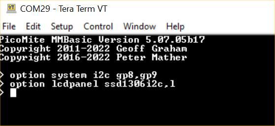 Edited 2022-08-27 04:49 by matherp |
||||
| lizby Guru Joined: 17/05/2016 Location: United StatesPosts: 3789 |
The option following SSD1306I2C is "orientation": "OR = This is the orientation of the display and it can be LANDSCAPE, PORTRAIT, RLANDSCAPE or RPORTRAIT. These can be abbreviated to L, P, RL or RP. The R prefix indicates the reverse or "upside down" orientation."" PicoMite, Armmite F4, SensorKits, MMBasic Hardware, Games, etc. on FOTS |
||||
| stanleyella Guru Joined: 25/06/2022 Location: United KingdomPosts: 2807 |
using this info from the manual I 2C Based LCD Panels The I 2C based display controllers use the SYSTEM I2C pins as per the pinout for the specific device. Other I 2C devices can share the bus subject to their addresses being unique. If an I 2C display is configured it will not be necessary to "open" the I 2C port for an additional device (I2C OPEN), I2C CLOSE is blocked, and all I 2C devices must be capable of 400KHz operation. The I 2C bus speed is not affected by changes to the CPU clock speed These panels are configured using the following commands. In all commands the parameters OR is the orientation of the display and it can be LANDSCAPE, PORTRAIT, RLANDSCAPE or RPORTRAIT. These can be abbreviated to L, P, RL or RP. The R prefix indicates the reverse or "upside down" orientation. PicoMite User Manual Page 44 OPTION LCDPANEL SSD1306I2C, OR [,offset] Initialises a OLED display using the SSD1306 controller with an I 2C interface. This supports 128 * 64 resolution. An additional parameter offset may be specified to control the position of the display. 0.96" displays typically need a value of 0. 1.3" displays typically need a value of 2. Default if omitted is 0. NB many cheap I2C versions of SSD1306 displays do not implement I 2C properly due to a wiring error. This seems to be particularly the case with 1.3" variants OPTION LCDPANEL SSD1306I2C32, OR Initialises a OLED display using the SSD1306 controller with an I 2C interface. This supports 128 * 32 resolution. what value pullup resistors please? using vbus ie 5V from usb to ssd1306 and ground. will sda and sck work from 3.3v logic? tried > option lcdpanel ssd1306i2c, L Error : Invalid Option Edited 2022-08-27 05:39 by stanleyella |
||||
| stanleyella Guru Joined: 25/06/2022 Location: United KingdomPosts: 2807 |
page 137 lots to learn thought it would be easy |
||||
| stanleyella Guru Joined: 25/06/2022 Location: United KingdomPosts: 2807 |
> option system i2c gp8,gp9 Error : Pin 11 is in use it is not connected. do I wipe and start again as it may be set for spi display? getting nowhere fast... but interesting |
||||
| stanleyella Guru Joined: 25/06/2022 Location: United KingdomPosts: 2807 |
> option system i2c gp6, gp7 'no error > option lcdpanel ssd1306i2c,l Error : Invalid Option |
||||
| stanleyella Guru Joined: 25/06/2022 Location: United KingdomPosts: 2807 |
it is only 2 wires 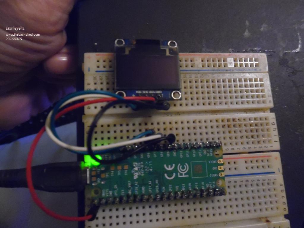 |
||||
| stanleyella Guru Joined: 25/06/2022 Location: United KingdomPosts: 2807 |
it is only 2 wires |
||||
| lizby Guru Joined: 17/05/2016 Location: United StatesPosts: 3789 |
When you want to report an error involving a pin usage, please provide your OPTION LIST output. For 3V3 devices, 10K pullup resistors will usually be appropriate. 4K7 for 5V devices. Also, a screen print when you get an OPTION error is better than typing what you thought you entered--you may not type what you actually entered. When you are quoting materiel (for instance, from the manual), you can use the "" icon (to the right of "code") to indicate what is quoted. If you're quoting from someone's post, use the "Quote" button. ~ Edited 2022-08-27 07:43 by lizby PicoMite, Armmite F4, SensorKits, MMBasic Hardware, Games, etc. on FOTS |
||||
| matherp Guru Joined: 11/12/2012 Location: United KingdomPosts: 11551 |
Start with OPTION RESET to clear anything there before. Then use the commands exactly as per my picture. You are using the PicoMite and not PicoMiteVGA firmware? 10K pullups will be fine but are probably already on the SSD1306 PCB Edited 2022-08-27 07:46 by matherp |
||||
| Mixtel90 Guru Joined: 05/10/2019 Location: United KingdomPosts: 8913 |
Start by going through the OPTIONS section of the manual, making sure that you know how to reset options. You can't always change how a pin works without resetting it first. There's no need to reload the firmware. Those displays work, no problem. Just giving you the answers won't teach you anything though. You need to look at how displays in general are set up, as well as how that particular one is handled. Mick Zilog Inside! nascom.info for Nascom & Gemini Preliminary MMBasic docs & my PCB designs |
||||
| stanleyella Guru Joined: 25/06/2022 Location: United KingdomPosts: 2807 |
Thanks @matherp. using picomite non vga. I used ssd1306 on 8bit and 4k7 pullups. option reset win disconnect reconnect sound. > option reset > option system i2c gp8,gp9 Error : Pin 11 is in use > rewired to gp6,gp7 > option reset > option system i2c gp6, gp7 'gets this far ok > option lcdpanel ssd1306i2c,l 'error Error : Invalid Option |
||||
| phil99 Guru Joined: 11/02/2018 Location: AustraliaPosts: 3296 |
It has to be exactly as Peter showed. You have this: > option lcdpanel ssd1306i2c,l It should be this: > option lcdpanel ssd1306i2c,1 l and 1 (L and One) look almost the same but MMBasic isn't interested in in looks! . Edit Correction I was thinking of the offset. OPTION LCDPANEL SSD1306I2C, OR [,offset] try this (with the spaces, just in case they matter) OPTION LCDPANEL SSD1306I2C, L ,1 Edited 2022-08-27 09:17 by phil99 |
||||
| lizby Guru Joined: 17/05/2016 Location: United StatesPosts: 3789 |
What does ?mm.device$, mm.ver report? What does OPTION LIST show? PicoMite, Armmite F4, SensorKits, MMBasic Hardware, Games, etc. on FOTS |
||||
| stanleyella Guru Joined: 25/06/2022 Location: United KingdomPosts: 2807 |
it seems it is option lcdpanel ssd1306i2c,LANDSCAPE, 0 where the last ,0 it defaults to if omitted. This is a 5V device but @lizby said "For 3V3 devices, 10K pullup resistors will usually be appropriate. 4K7 for 5V devices." 10K pullups to 5V or 3.3V? 'are they needed for a bread board project ie short wires? Running ssd1306 from vbus 5V... I have tried running it from 3.3V. hence pullup question. I think it is not as simple as spi for display. Sure the sda,scl lines are 3.3V logic? |
||||
| matherp Guru Joined: 11/12/2012 Location: United KingdomPosts: 11551 |
Never connect anything over 3.6V to any RP2040 pin |
||||
| matherp Guru Joined: 11/12/2012 Location: United KingdomPosts: 11551 |
Not sure how to make this any easier 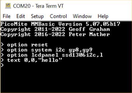 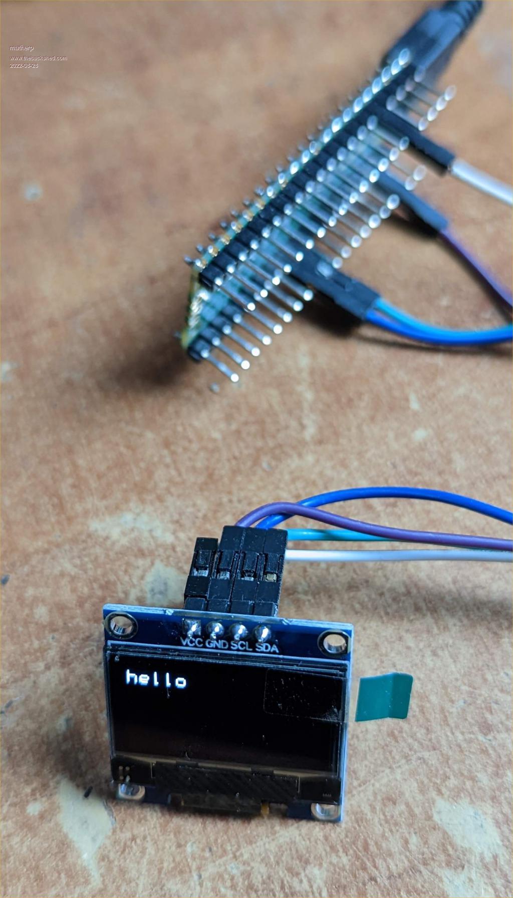 Connections: SSD1306 VCC to PicoMite 3.3V SSD1306 GND to PicoMite GND SSD1306 SDA to PicoMite GP8 SSD1306 SCL to PicoMite GP9 No resistors needed just 4 link wires |
||||
| stanleyella Guru Joined: 25/06/2022 Location: United KingdomPosts: 2807 |
Mik testing nothing works with 2 ili9341 that do work teraterm > option reset > option system i2c gp8,gp9 Error : Pin 11 is in use > option system i2c gp8,gp9 Error : Pin 11 is in use > option lcdpanel ssd1306i2c,l Error : Invalid Option > yawn. forget i2c expanders |
||||
| stanleyella Guru Joined: 25/06/2022 Location: United KingdomPosts: 2807 |
what is not apparent is setting say touch and sd card and display but then using something new like a sdd1306 after using ili9341. Start again and the reset from geoffs site |
||||
| Page 1 of 3 |
|||||
| The Back Shed's forum code is written, and hosted, in Australia. | © JAQ Software 2026 |
