
|
|
Forum Index : Microcontroller and PC projects : GCODE FOR FRONT PANEL ENGRAVING
| Page 1 of 2 |
|||||
| Author | Message | ||||
OA47 Guru Joined: 11/04/2012 Location: AustraliaPosts: 1050 |
I have been producing front panels for projects by writing simple GCODE for the control holes, display area cutout, mounting screws and perimeter cutout with an origin at the bottom left-hand side of the panel. I wish to add code to label the controls etc and have some software to generate the GCODE for the lettering. Unfortunately, the software to generate the lettering references the origin to the bottom left-hand side of the first letter. Other than going through the whole lettering code and adding the offset for all of the x and y values, is there a way of adjusting the origin in the GCODE so I can cut and paste the text lettering into the full code for each of the pieces of text? 0A47 |
||||
| Malibu Senior Member Joined: 07/07/2018 Location: AustraliaPosts: 261 |
What software are you using to generate the code? John |
||||
| OA47 Guru Joined: 11/04/2012 Location: AustraliaPosts: 1050 |
I am using Liteburn to generate the text GCODE and I am using Candle to send to the cutter/engraver. 0A47 |
||||
| Malibu Senior Member Joined: 07/07/2018 Location: AustraliaPosts: 261 |
When you create the text in Liteburn, there's a couple of dropdowns for 'Align X' & 'Align Y' [Left, Middle, Right] & [Top, Middle, Bottom] Have a play with those settings, they might help Sorry, I don't know Candle Edited 2024-12-01 08:07 by Malibu John |
||||
| OA47 Guru Joined: 11/04/2012 Location: AustraliaPosts: 1050 |
Sorry John, old age is creeping in, I should have said Litefire instead of Liteburn. It is the POV version of software that is supplied with the Laser engraver. 0A47 |
||||
| Malibu Senior Member Joined: 07/07/2018 Location: AustraliaPosts: 261 |
Yup, I hear you there!  Can't help with LiteFire, but there might be a few options : 1) In most software, you can generally highlight the text and it will generate 9 'handles'... click and hold the center one and it will usually enable a drag function. You might be able to drag it to a predetermind snap position where you need it. 2) I use Aspire, and highlighting a vector, I can call a move command and select 'absolute' or 'relative'. Just enter the cooridates, and it will postion the element regardless of where the origin was set to. Maybe you can find something similar. 3) highlight the text and jog the position with the arrow keys? Hope it helps  John |
||||
| DaveJacko Senior Member Joined: 25/07/2019 Location: United KingdomPosts: 103 |
I' ve done something similar,so it can't be very difficult. pity I can't remember exactly how, but suspect I used Absolute and Relative modes in GRBL on my CNC3018 Position your first letter with Absolute co-ordinates, then invoke Relative co-ords, G-Codes G90 and G91 are absolute and relative, respectively. I think I used the free "stickfont" program to produce a basic vector font, regs Dave Try swapping 2 and 3 over |
||||
| OA47 Guru Joined: 11/04/2012 Location: AustraliaPosts: 1050 |
Dave you are going down the road that I had hoped to go. I played with the G90 and G91 codes but unfortunately it made a mess. If I read you correctly, are you saying that if I want a positive offset of X50 Y90 then I would run my cutting code retorn to X0 Y0 then G91 followed by G01 X50 Y90 then a G90 would make this a new origin? 0A47 |
||||
| ElectroPI Regular Member Joined: 27/04/2012 Location: AustraliaPosts: 42 |
Hi, Check out DeskEngrave: http://deskam.com/deskengrave.html It allows you to - use any Windows True Type font - write text in an arc or straight line - allows you to offset the text from 0,0 - generates G-code or DXF I haven't used it for ages but in my notes.txt file it says - you can set width or height of text but not both - 'depth' is depth of cut - 'rapid height' is how high it lifts the cutter between cuts - 'precision' - not sure but I use 10 - 'dec places' - use 3 for high precision - when you change fonts, press the F button on the left to apply it - there's no G20 or G21 command so insert one into the G-code to select imperial or mm. Also check out Candle for creating & sending your G-code file: https://github.com/Denvi/Candle You can load a G-code file and see it in 3D. But it also allows you to write the code from scratch. As you type in each line of G-code it draws each bit in the 3D window as you go. So you should be able to write G-code to create and machine your panel. Then load the G-code file from DeskEngrave to machine your text. regards |
||||
| OA47 Guru Joined: 11/04/2012 Location: AustraliaPosts: 1050 |
I think my understanding of the G90 and G91 codes is in error. Here is a snippet of the GCODE I am using: G1 X2 Y2 ;STARTING POINT G1 Z4 ;RAISE Z AXIS TO 4mm ;****************************************************************** M5 ;SPINDLE OFF ;END OF FRONT PANEL ROUTING ; ;CHANGE TO LASER MODULE ;****************************************************************** ;ADD TEXT LABELS FOR POSTS ;GND OUT IN X8MM TEXT ;OFFSET TO TEXT FROM DATUM X150 Y20 G01 X150 Y20 G91 ;****************************************************************** S1000 G21 F2000 G1 X3.4065 Y5.3677 G90 M03 G1 X3.2000 Y5.4194 G1 X3.0452 Y5.4710 G1 X2.8903 Y5.5226 G1 X2.6839 Y5.5742 G1 X2.5290 Y5.6258 G1 X2.3226 Y5.6258 G1 X2.0645 Y5.6258 G1 X1.8581 Y5.5742 G1 X1.7032 Y5.4710 G1 X1.4968 Y5.3677 G1 X1.3419 Y5.2645 G1 X1.2387 Y5.1097 G1 X1.1355 Y4.9548 G1 X1.0323 Y4.8000 G1 X0.9290 Y4.5935 G1 X0.8774 Y4.3871 G1 X0.8774 Y4.1290 The router returns to the DATUM after routing the FRONT PANEL and I move to the DATUM OFFSET (150mm to the right and 20mm up) for the label to be lasered. At this point I invoke the G91 and indeed the next move does leave from the new point but all following moves leave from the preceding point until I invoke the G90 but then all following moves are referenced back to the original DATUM. More help needed  0A47 |
||||
| Malibu Senior Member Joined: 07/07/2018 Location: AustraliaPosts: 261 |
I don't manually edit gcode very often - I let the PP take care of all those movements. From my limited knowledge, if you change to Incremental Mode, the positions are now measured from the CURRENT postion. Switching back to Absolute Mode, the postions reference now revert back to the DATUM position So this .... to my understanding, says : 1/ goto X150, Y20 (relative to origin) 2/ change to move everything relative from the current postion 3/ add 3.4064 to the current X, add 5.3677 to the current Y and goto that position 4/ change to move everything relative to the origin setting (X0, Y0, Z0) 5/ goto X3.2, Y5.4194 (relative to origin) 6/ etc, etc... Line 5 says go back to postion X3,Y5 Edited 2024-12-02 13:20 by Malibu John |
||||
| OA47 Guru Joined: 11/04/2012 Location: AustraliaPosts: 1050 |
I have looked at DeskEngrave and it does as you say but it exports GCODE as a .Dnc file which needs a lot of manipulation to use. I have been using Candle as my preferred CNC software for some years now. 0A47 |
||||
| ElectroPI Regular Member Joined: 27/04/2012 Location: AustraliaPosts: 42 |
I haven't found that at all. I just tried a test .dnc file in Candle and it handles it without any problems. But I normally name my files with the extension .txt so they open in Candle and Notepad++ easily. Just make sure in DeskEngrave you set a value for the Feedrate and Plunge Rate otherwise you'll get an F0 in the G-code which Candle doesn't like. If you use Candle to send the G-code file to grbl (I use an Arduino Uno), use the jog buttons to position where you want the text to start. Then just press the Zero XY and Zero Z buttons to make that position 0,0,0. Alternatively you can use the G92 G-code command. In the box at lower right of Candle's screen just type G92 X0 Y0 Z0 and the Work Coords will become 0,0,0. I use this all the time when I want to set the height of the cutter eg I lower the cutter using very small jogs until it just touches a scrap piece of aluminium which I previously measured. Say it's 5.03mm. As soon as the cutter touches the metal I type G92 Z5.03 into the Console command box and the Z coord becomes 5.03mm. regards |
||||
Revlac Guru Joined: 31/12/2016 Location: AustraliaPosts: 1277 |
Is it worth putting in limit a switch? everything else had them except for the little cnc. I did use Inkscape and JScut a few times, JScut hasn't been updated to my knowledge but it did have Z origin etc. https://www.thebackshed.com/forum/ViewTopic.php?FID=11&TID=15051 not sure if that is any help but interested to see how you go with text, I want to do text stencils, have to find the font that I like. Cheers Aaron Off The Grid |
||||
| OA47 Guru Joined: 11/04/2012 Location: AustraliaPosts: 1050 |
Because the .DNC files have line numbers if I want to merge the code into an existing .NC file then each of the lines must be modified. 0A47 |
||||
| ElectroPI Regular Member Joined: 27/04/2012 Location: AustraliaPosts: 42 |
Just load your panel file and machine all the holes. Then load a label file, re-position the tool, zero its position and machine a label. Repeat the last line for each label. Might be a bit time consuming for lots of labels but it should work. Handy that DeskEngrave can produce curved labels too!! |
||||
| ElectroPI Regular Member Joined: 27/04/2012 Location: AustraliaPosts: 42 |
OK just learnt something today.... Open the .dnc file in Notepad++ In main menu select Search, Replace In the popup box put ^N\d+\h into the Find what box. Leave the Replace with box empty. In Search Mode select the Regular Expression button. Click the Replace All button. All line numbers will be removed. Apparently ^ means start of line N is literal \d means digits + means match the preceding atom one or more times \h means horizontal spaces 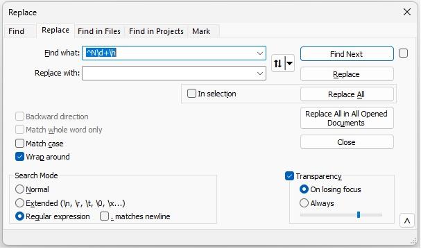 |
||||
| OA47 Guru Joined: 11/04/2012 Location: AustraliaPosts: 1050 |
The reason that I want to merge the GCODE is so that I can be sure that the labels are accurately located to the cutouts of the panel. I can view both the cutouts and the TEXT labels in the 3d viewer of the CANDLE software. 0A47 |
||||
disco4now Guru Joined: 18/12/2014 Location: AustraliaPosts: 1127 |
If you are on windows it looks like Stickfont will generate the letters referencing the machine origin. 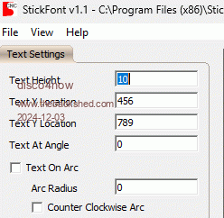 F4 H7FotSF4xGT |
||||
| OA47 Guru Joined: 11/04/2012 Location: AustraliaPosts: 1050 |
Played around with stick font and it looks like it will suit my purposes. Thankyou disco4now 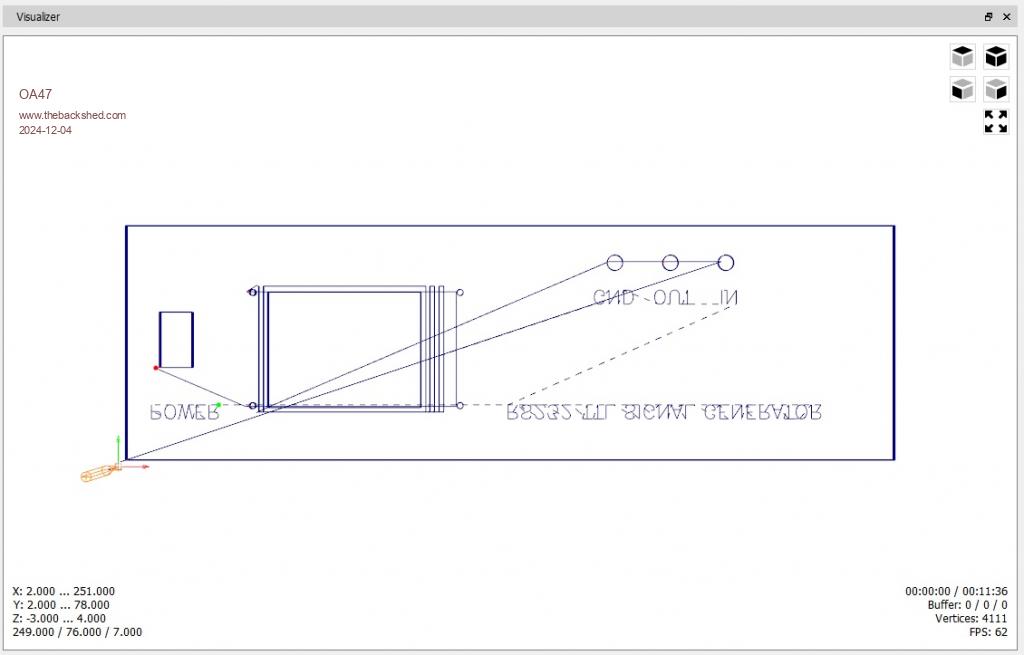 0A47 |
||||
| Page 1 of 2 |
|||||
| The Back Shed's forum code is written, and hosted, in Australia. | © JAQ Software 2026 |
