Notice. New forum software under development. It's going to miss a few functions and look a bit ugly for a while, but I'm working on it full time now as the old forum was too unstable. Couple days, all good. If you notice any issues, please contact me.
Solar Mike Guru Joined: 08/02/2015 Location: New ZealandPosts: 1247
Posted: 10:51am 11 Aug 2026
Copy link to clipboard
Print this post
One very glamorous device we have on site is a sewerage tank fitted with a large cast stainless macerating pump, about 230 vac 2HP motor, sometimes its difficult to start, we run it direct off a 7.5KVA generator couple of times a week, 10 minutes or less each duration. At times the generator doesn't produce enough grunt to start the pump, it will bog the generator down, flicking the circuit breaker off and on a few times gets it running. Once running draws 10 amps or so.
Our main 6 kva 48v - 230vac inverter wont start it either, especially when other pumps are running off it.
What I was thinking was build a small 230 vac inverter that can supply 15 kw or so for a few seconds to get the pump running. Because the on time is quite short possibly I could get away with a small iron toroidal core as it would have a long thermal lag before getting too hot.
Possibilities might be use 100v dc for the inverter from a small pack of 50 AH lifepo4 cells and dedicate this just for this pump.
Or use DC from another source, start the inverter and synchronize with our main inverter power on the site, then turn the pump on, once running disconnect and leave it powered from the site supply.
Anyone have any ideas.....
Cheers Mike
Revlac Guru Joined: 31/12/2016 Location: AustraliaPosts: 1302
Posted: 01:22pm 11 Aug 2026
Copy link to clipboard
Print this post
Interesting, I have a similar problem with a old bench grinder (it used to dim the lights on grid power when starting), would often not start even though the generator was plenty powerful enough to run it, it would kill the generator and the grinder would just start to spin but not pickup before the breaker trips or gen stalls, Big inverter just kicked its backside and it starts every time.
Perhaps lower voltage lower frequency start ramp 2 seconds etc, experiment perhaps.Cheers Aaron Off The Grid
phil99 Guru Joined: 11/02/2018 Location: AustraliaPosts: 3360
Posted: 01:39pm 11 Aug 2026
Copy link to clipboard
Print this post
Lower frequency will almost certainly require a bigger start capacitor as its reactance will be higher at the lower frequency.
A bigger start capacitor might be worth a try on its own as some manufacturers use the smallest one they can. A bigger one (or another in parallel) may get it moving quicker. If that results in too much current in the start winding put a suitable PTC thermistor in series with the extra capacitor to cut it out after a second or two.
kentfielddude Senior Member Joined: 09/05/2019 Location: United StatesPosts: 111
Posted: 04:31pm 11 Aug 2026
Copy link to clipboard
Print this post
Soft Start - Altistart 01
soft start Maybe something like this could work. Edited 2026-08-12 02:31 by kentfielddude
Revlac Guru Joined: 31/12/2016 Location: AustraliaPosts: 1302
Posted: 09:15pm 11 Aug 2026
Copy link to clipboard
Print this post
Be very careful adding a large capacitor over the existing size, it will increase start toque and surge sometimes to s huge amount and has in some multi stage pumps screwed the shaft off from such a violent start, will also use more power and heat the motor, the surge will be shorter. (Can be More difficult for inverter or generator to start it) I have seen a motor take off across the floor even though it was clamped, the start was so violent, it had a different capacitor on the manual compared to a rough stamped nameplate value.
Likely know this already. Edited 2026-08-12 07:20 by RevlacCheers Aaron Off The Grid
Godoh Guru Joined: 26/09/2020 Location: AustraliaPosts: 701
Posted: 09:39pm 11 Aug 2026
Copy link to clipboard
Print this post
HI Mike, I am guessing the pump is actually in the tank which makes stuff harder. I have an hydraulic wood splitter that my inverter can not start. I drilled a hole in the fan end of the shaft and put a bolt in there, I use a battery drill to spin the motor up to speed a bit then hit the start button. Once the motor gets started it is fine the inverter can run it no problems.
Obviously if the pump is a submersible then that gets much harder.
I don't know what battery bank you have but I added a 500 farad capacitor bank in parallel with our VRLA batteries to help with starting current. All my power tools and compressor start as if on mains power. It is only the hydraulic splitter that has problems. My system is 24 volt so that makes stuff a bit harder.
Bryan1 Guru Joined: 22/02/2006 Location: AustraliaPosts: 2227
Posted: 10:01pm 11 Aug 2026
Copy link to clipboard
Print this post
Hi Mike that madboard I made starts everything I have thrown at it and just works Sometimes my little air compressor will go chug chug then fire into life and sometimes it just starts it normally. With my mig welder I found using 110 amps the brandnew 16 amp circuit breakers tripped so I do need to source some 25 amps ones.
My old 8" bench grinder sat for over a decade so I thought I would test it and sure enough the inverter started it and for the first time I saw a 20Kw surge on the readout, now as it has been pointed out the power factor would of come into play but I am very happy with the performance of the madboard which will soon break the 200Kw/h mark.
Regards Bryan
Solar Mike Guru Joined: 08/02/2015 Location: New ZealandPosts: 1247
Posted: 03:10am 12 Aug 2026
Copy link to clipboard
Print this post
Thanks for the thoughts so far, Yes the macerating pump is fully submerged 2M down in a tank of crap buried in the ground, so any change in start caps etc isnt possible. I think so far, a small LF inverter that will run for 5 min without over heating maybe the easiest solution.
We have a 900AH 48v bank of lead carbon batteries, prob needs about 15 Kw peak power, that's what about 350 amps to get the pump started. Feel happier with 100v input DC to get the current down, 24v dont think would be possible; I do pull apart old Lifepo4 failed 48v sealed battery banks apart from time to time, they usually have 16 or 32 x 100AH cells in them, the retailer has to dump them as its uneconomic to fix and NZ has no Lifep04 re-cycling. Will see what I can scrounge up...
Revlac Guru Joined: 31/12/2016 Location: AustraliaPosts: 1302
Posted: 10:28am 12 Aug 2026
Copy link to clipboard
Print this post
I pretty sure that will scare the crap out of it Cheers Aaron Off The Grid
analog8484 Senior Member Joined: 11/11/2021 Location: United StatesPosts: 212
Posted: 03:31pm 12 Aug 2026
Copy link to clipboard
Print this post
I've wondered about how well parallel caps would really help with starting power.
Have you measured the actual starting power boost from the caps? And for how long?
Did you have to change the inverter to support the higher starting power?
Godoh Guru Joined: 26/09/2020 Location: AustraliaPosts: 701
Posted: 09:46pm 12 Aug 2026
Copy link to clipboard
Print this post
Hi Analog, no i have not measured how much current the capacitors add when starting heavy loads. I did not change the inverter at all, it is an Aliexpress 5kw board, with a home made transformer.
The system used to struggle a bit when starting my air compressor, so the compressor would be quite slow to start up , but after adding the 500 farad bank in parallel with the batteries it always starts up fast. I also had problems with blowing up an old PowerJack 8kw inverter that I had too. It blew up a couple of times starting and running my sliding compound saw which was a universal 1800 watt motor. I used the transformer cores from the powerjack and stacked them to make the new inverter. Have not had an inverter problem now for about 4 years. I will put my clamp meter on the caps next time I start the compressor and see if it is fast enough to pick up the current they output. Pete
InPhase Senior Member Joined: 15/12/2020 Location: United StatesPosts: 181
Posted: 02:25pm 14 Aug 2026
Copy link to clipboard
Print this post
That motor is probably peaking at 50-70 or more amps trying to start, but the generator can only give it 31. You could make a timed circuit using an SCR module or really large AC solid state relay that bumps the power like you do with the breaker to get it moving. Give it 100 ms on, 100 ms off, then 150 ms on, 150 ms off, then 250 ms on, etc. until fully started. A 150 amp SCR would probably do the trick. Put an RC snubber across the switching device.
Solar Mike Guru Joined: 08/02/2015 Location: New ZealandPosts: 1247
Posted: 10:26pm 14 Aug 2026
Copy link to clipboard
Print this post
Interesting idea, I did some research, the generator is a permanent magnet type, so has no field winding and thus no feed back mechanism to boost output voltage with load. On applying load the generator output could start collapsing which means even less torque from the motor, so it never gets out of the stall condition.
Some sort of ramped start sequence may work, you must be able to buy something that does this off the shelf.
phil99 Guru Joined: 11/02/2018 Location: AustraliaPosts: 3360
Posted: 01:12am 15 Aug 2026
Copy link to clipboard
Print this post
I am quite surprised that 7.5kVA permanent magnet generators exist. The largest I ever encountered was 800W. It relied on stator saturation to limit the output voltage which resulted in a very distorted waveform at low load. Comparing the stator with a similar size motor revealed the width of the laminations between the outer diameter and the bottom of the slots of the stator was quite small, causing it to saturate at low load.
Another was a 300W Honda that had a normal stator and used a saturable inductor across the output. Without the inductor at low load the open circuit voltage would exceed 300V.
With both of these generators the saturation voltage was strongly affected by the frequency, rising with increasing engine speed, so an accurate governor is required. I imagine in your case the start current is causing the engine speed to fall which reduces the voltage to the point where the motor wont start.
Perhaps you could experiment with the governor adjustment, increasing the no-load frequency to 60Hz or more. This might increase the output voltage enough to get the motor started.
For a permanent solution some means of increasing the speed just before starting the motor then returning the governor to 50Hz after starting may be needed. Maybe a PicoMite or MicroMite controlling a motor contactor and solenoid connected to the governor could do it.
Edit. Another simpler trick that I forgot to mention is to first have the generator working hard to get the engine up to full working temperature before starting the motor. Two or three 2kW heaters may be enough. Switch them off at the same instant you switch the motor on. The throttle will then already be wide open before the inrush current rather than the governor waiting for the speed to fall before opening the throttle. Edited 2026-08-15 14:55 by phil99
Revlac Guru Joined: 31/12/2016 Location: AustraliaPosts: 1302
Posted: 05:21am 15 Aug 2026
Copy link to clipboard
Print this post
Just tested the saw bench motor (it has centrifugal start switch) on the Mad Inverter 230Vac Inrush/start surge 23.5Amp, now Put the Triac controller on, wound it down a bit and plugged in the Saw bench and started it a few times at different settings, it was drawing 17.5 amp did take a little longer to reach full speed, about a second or so, wouldn't want to go less than that, it did make the inverter growl a bit, I don't need to do this anyway, but have done this to test a few motors.
I haven't seen a large permanent magnet generator up close, The Generator I have with a PMG on it is the Large Stamford genset with an expensive AVR, its Brush-less like a few others here.
Just remembered I have a 2HP pump, think its hiding from me. I suspect it might not like the Triac controller. Edited 2026-08-15 18:01 by RevlacCheers Aaron Off The Grid
Solar Mike Guru Joined: 08/02/2015 Location: New ZealandPosts: 1247
Posted: 01:19am 22 Aug 2026
Copy link to clipboard
Print this post
Looking at various options, have decided to build a LF inverter, I have an old toroidal core stripped out of a variac, the core needs demagnetization, so will have a go doing that. Also have a mishmash of various Lifepo4 cells here, just wasting away in my shed, so could use them to make a 32 cell battery for nominal 105V output. Sounds like a lot of work... the fun things we do as a hobby.
100v DC input makes things easier to build an inverter as the currents are smaller than your normal 50v, so pcb's augmented by busbars are easier to DIY. To that end have decided to go with 3 parallel mosfets per bridge quadrant, mounting them under the main pcb bolted face down to the bottom of the case - 2mm thick alloy.
As high voltages and large currents switching in 100's nSec time frames, construction is akin to RF design techniques to minimize voltage spikes and wave form ringing; the main 2 layer power pcb is built as a sandwich construction with 0v on the bottom, 100v on the top layer and the AC switch nodes as an isolated floating busbar glued to the top layer. Thinking around the 150A max and 100v, should be plenty to run the pump, the high start current is seconds only, normal running approx 20A for about 10 minutes, couple of times a day.
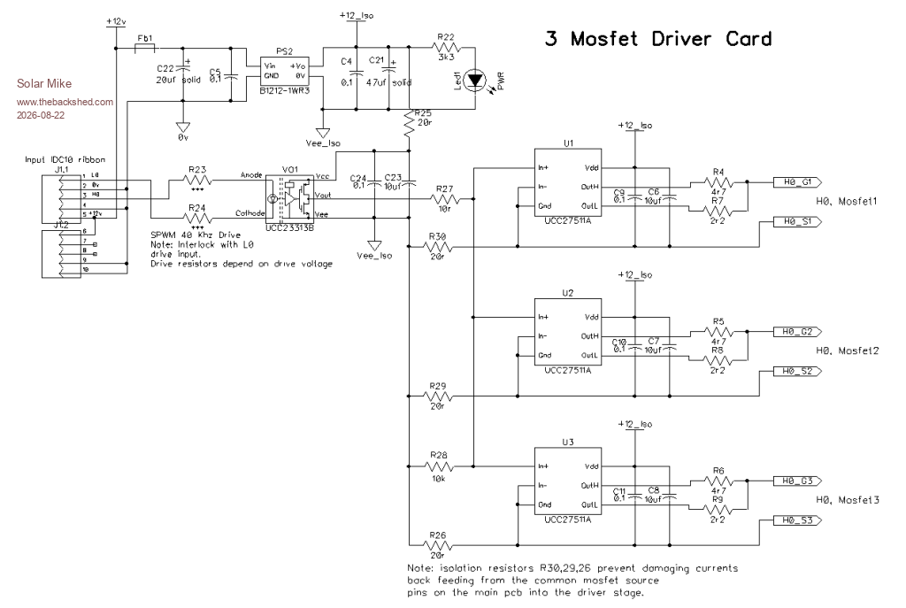
Each group of 3 mosfets have their pins protruding from the main pcb, and a driver daughter pcb sits vertically off this. Have used an "E-Diode" UCC23313B isolated mosfet driver as the main pwm input to each card, the output of this driver drives 3 x UCC27511A drivers, one for every mosfet. CPU derived inputs to the card have both High side and Low side inputs, this allows H0,L0 driver cards be cross-coupled in an interlock arrangement, ensuring no possibility of shoot-thru occurring, should the cpu go haywire. SPWM + dead-time generated from the PICO2-RP2350 cpu PIO, is 40 Khz, so the drivers have to be robust.
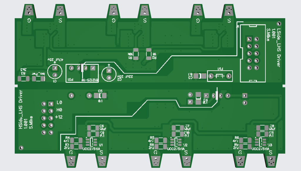
This time I have a schematic, here is my provisional for the driver cards, 4 cards each 28mm high and 96mm long, 2 per pcb 1.2mm thick, makes it easy to cut in half. Unfortunately due to their mounting positions, components have to be on the correct side, thus 2 different layouts.
Driver PCB:
Will draw up the schematic for the main Bridge board next.
Mike
Godoh Guru Joined: 26/09/2020 Location: AustraliaPosts: 701
Posted: 12:26am 23 Aug 2026
Copy link to clipboard
Print this post
Analog, I finally got around the checking the current on my capacitor bank. Just as well I did as I found the reason my machines were starting slower than usual. I had a 250 amp fuse on the capacitor output, and found that the fuse holder had melted a bit and the fuse had blown. So I replaced it with a circuit breaker and tested the current on the air compressor on start. The clamp meter I have is digital so may not be fast enough to give the full picture but the capacitor current jumped up to 95 amps on start then dropped back to about 45 amps after a second or two. Finding that fault on the fuse holder and deleting it is great as my 2.2 kw wood splitter draws a lot of current on start and last time I used it, it was having trouble starting, even when using my battery drill as a starter motor. Pete
Solar Mike Guru Joined: 08/02/2015 Location: New ZealandPosts: 1247
Posted: 02:43am 23 Aug 2026
Copy link to clipboard
Print this post
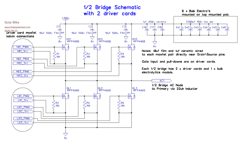
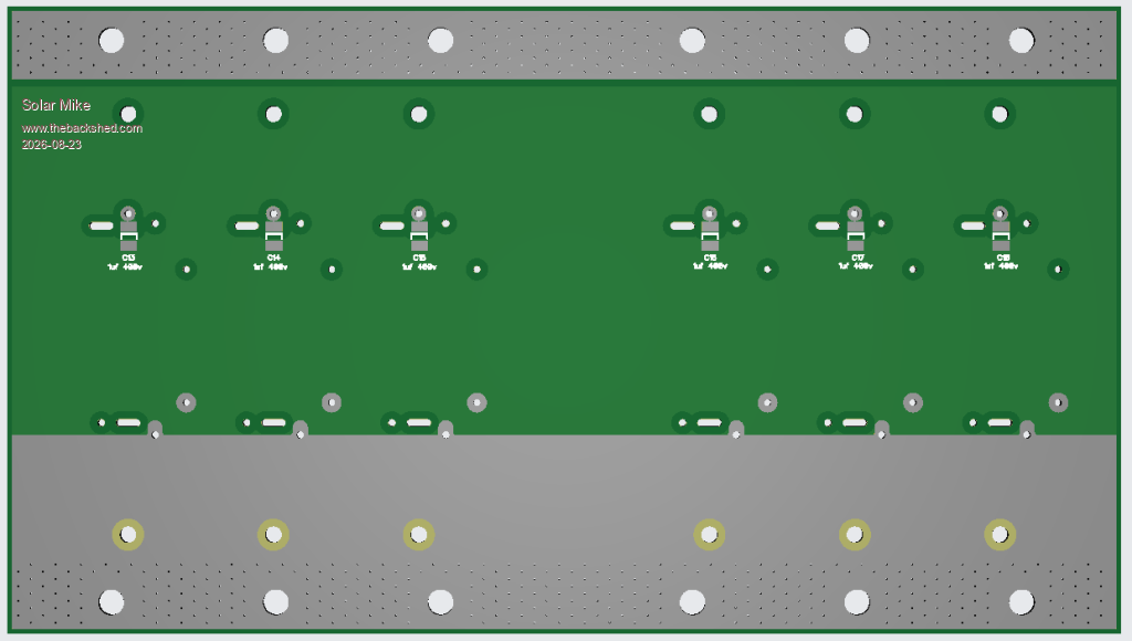
Here's the schematic for 1/2 of the bridge, the two H0,L0 driver cards sit directly on the pcb mosfet pins to give a direct kelvin drive connection. For a 100v nominal battery rail I'm using IRFP4668 mosfets with a 200v rating, It maybe possible to use lower voltage rated devices after observing them with a scope, the amplitude of any inductive spikes is unknown, so better safe than sorry.
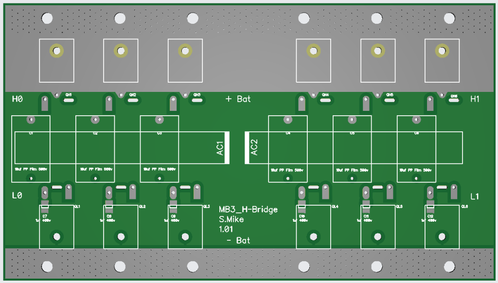
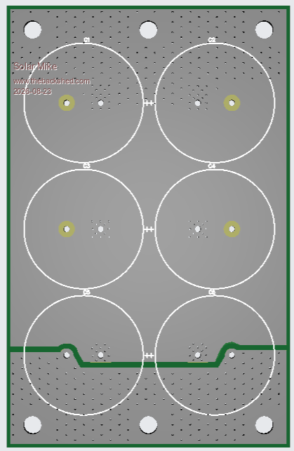
For the very fast transients I have a 1uf ceramic across each mosfet H\L pair and a 10uf 500v pp film capacitor for main commutation current surge. This combination should ensure the bulk electrolytics sitting on another sandwich constructed pcb above the main board have minimal very high frequency current, which large electro's are not very good at handling anyway. Mosfets sit under the pcb, face down, the AC node connection is a folded copper foil soldered to the AC busbar and thru the pcb slot to the mosfet pin.
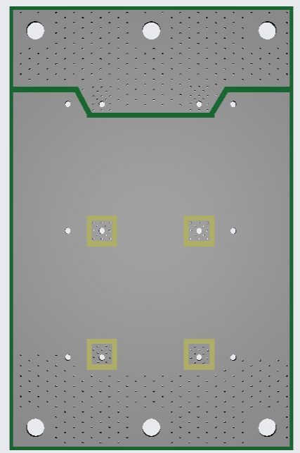
Top and bottom of the main pcb has 0.5mm thick copper foil folded over the edge and soldered to the pcb. Same for each bulk cap board, 7mm dia brass spacers link these boards together. The two AC nodes comprise a copper bar 15 x 2mm thick glued to the main pcb on a piece of FR4 with no copper as insulation, this sits under the 10uf film caps. The two bulk cap boards have 0.25mm copper foil added top and bottom to increase current capacity.
Main AC outputs each have a 40uH inductor to the transformer primary, this acts as the 40 Khz filter and isolates the primary and its winding capacitance from 40 Khz HF spikes; this allows a second identical bridge to also be connected in parallel to the transformer input for greater output; as they will all share identical SPWM from the cpu.
Haven't even looked at the cpu drive board yet, PICO2 RP2350 module, using the PIO to produce accurately timed 40 Khz SPWM + dead-time, will be using feed forward voltage sensing as the primary output AC stabilization and a secondary feedback measuring the output voltage.
Maybe awhile before I get around to working on this, too many other projects on the go at the moment, along with a bathroom renovation...
Bridge PCB, 230 x 130mm:
1 of 2 Cap pcbs: 83 x 130mm:
I'm not going to get any of these boards made yet, until the cpu pcb is done, as there maybe changes; looked at the cost of 2oz pcb, its horrendous, the most cost efficient way to get them made is to do all as a single pcb with snap off cut lines.
Cheers Mike Edited 2026-08-23 12:54 by Solar Mike
analog8484 Senior Member Joined: 11/11/2021 Location: United StatesPosts: 212
Posted: 04:29pm 23 Aug 2026
Copy link to clipboard
Print this post
Thanks for checking Pete. It's impressive that the 250A fuse was blown and the fuse holder started to melt. That suggests the the peak caps current was likely way higher than 95A and probably quite a bit higher than 250A too since the surge is only a couple seconds. It's good to know the caps can really provide the boost power. OTOH, one thing I've wondered is how charging and discharging could be practically controlled for such caps without complex add-on's. I would appreciate it if you could post update on how the new breaker holds up over time.
analog8484 Senior Member Joined: 11/11/2021 Location: United StatesPosts: 212
Posted: 04:51pm 23 Aug 2026
Copy link to clipboard
Print this post
Looking forward to seeing the build. It's a bit surprising to see a 40uH inductor given the 40kHz switching frequency. Based on the ~47uH inductor sizing for the 20kHz switching frequency used in the more recent nanoverter builds, it seems a significantly smaller inductor could be used for 40kHz. Increasing the switching frequency is one thing I've wondered about for the nanoverter as a way to reduce the quite large inductor size used in the recent builds.
Page 1 of 2
Print this page
The Back Shed's forum code is written, and hosted, in Australia.

 Notice. New forum software under development. It's going to miss a few functions and look a bit ugly for a while, but I'm working on it full time now as the old forum was too unstable. Couple days, all good. If you notice any issues, please contact me.


 Print this post


 Sometimes my little air compressor will go chug chug then fire into life and sometimes it just starts it normally. With my mig welder I found using 110 amps the brandnew 16 amp circuit breakers tripped so I do need to source some 25 amps ones.