
|
|
Forum Index : Windmills : Ax -Fx New High & Major Failure
| Page 1 of 2 |
|||||
| Author | Message | ||||
fillm Guru Joined: 10/02/2007 Location: AustraliaPosts: 730 |
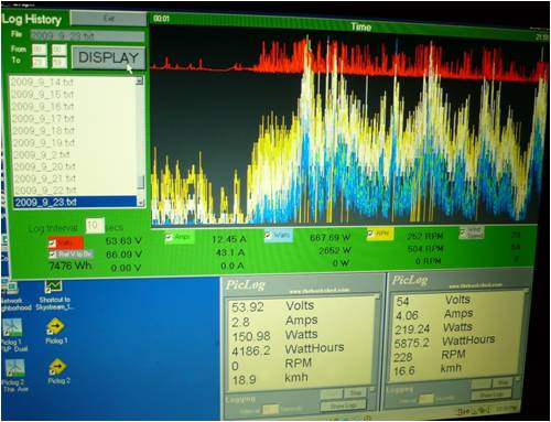
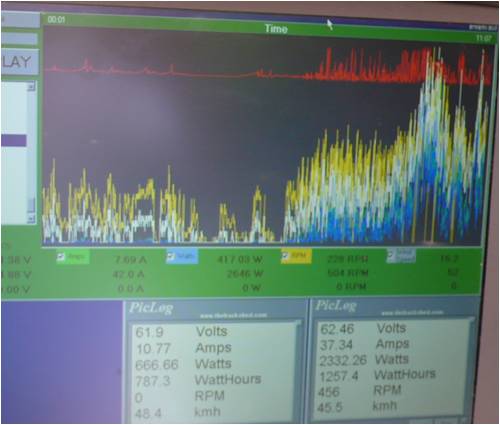
Hi All , All happened a couple of weeks ago when the dust storm hit Brisbane , a freeky event with lots of wind and dust . In the middle you could look directly at the sun as it was just a big white dot in the sky and by the end of the day the Ax Fx had produced over 6000 Whrs and the F&P Dual over 4000 Whrs setting a new high for a day of over 10Kw , the Ax Fx also hit a new max output of 2.6Kw @ 500 Rpm 
After that I had to fly out to work and a couple of days later another front went through when this happened 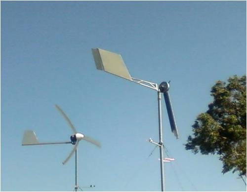
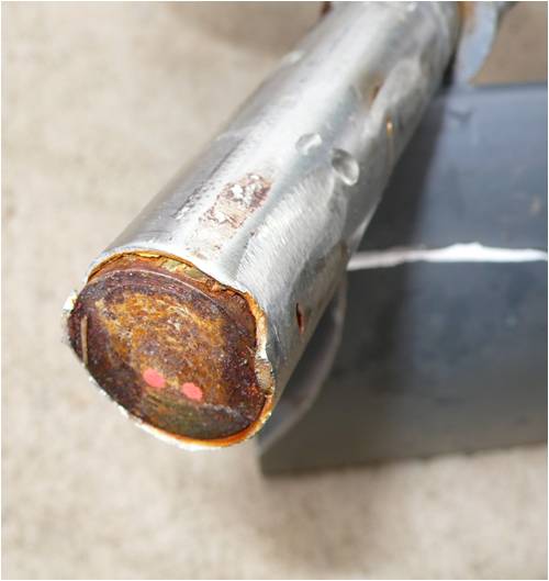
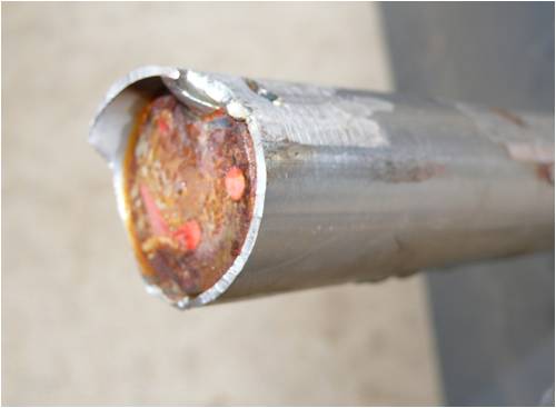
Below are some close ups of the failure , I have a pretty good idea of why it happened and what caused the first blade to fly of , the second blade came of due to the same failure but was accelerated because in the confusion the wrong shut down switch was thrown and the mill ran unloaded with two blades untill the second blade let go . I'll leave it to some of the forum members to have their conclusions .. 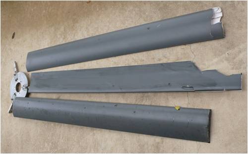
I have heard of another set of blades having a similar failure , hopefully the pics for that will get posted as well... PhillM ...Oz Wind Engineering..Wind Turbine Kits 500W - 5000W ~ F&P Dual Kits ~ GOE222Blades- Voltage Control Parts ------- Tower kits |
||||
gpalterpower Senior Member Joined: 19/07/2009 Location: AustraliaPosts: 177 |
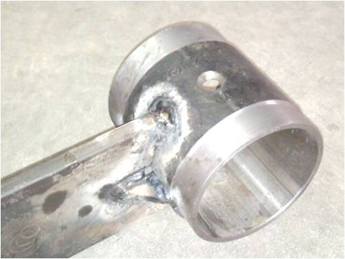
Ouch Phil!!!....thats gotta hurt, especially after those record results you attained! So was it due to one of the blades hitting the pole which started the chain reaction, a clamp coming loose or rivets? I had been following the construction of your dual mill and have been modelling my mill along similar lines(progress slow but some pics included), but I think I may have to change my plans a little. Looks like your blade mounting plate held up.!! Regards Marcus 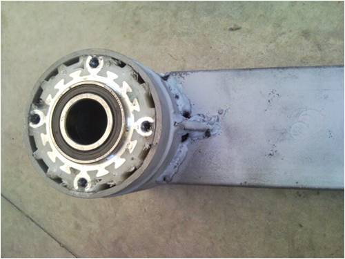
if it aint broke dont fix it!! |
||||
| fillm Guru Joined: 10/02/2007 Location: AustraliaPosts: 730 |
Marcus, the bearing hub to arm mount has to be able to take everything mother nature has to throw at it , and then some , the forces generated at the point where it welds to the arm are extreeme . It appears you did not grind the galvanizing of the pipe before welding , not only does this give off poiseness gas , it makes it hard to get a good weld with good penetration. I would suggest to clean some of those sl*g inclusions out and lay some more weld on to make sure it will not let go. This is probably a little off topic for this , but keep up the good work... PhillM ...Oz Wind Engineering..Wind Turbine Kits 500W - 5000W ~ F&P Dual Kits ~ GOE222Blades- Voltage Control Parts ------- Tower kits |
||||
JimBo911 Senior Member Joined: 26/03/2009 Location: United StatesPosts: 262 |
Phill Woooooooooo can't tell you how bad where feeling over here, my heart hit the floor when I seen your post I can only imagine how your feeling? Looks as if only the blades are damaged and everything else is OK? Jim |
||||
| Jarbar Senior Member Joined: 03/02/2008 Location: AustraliaPosts: 225 |
Phil sorry to see your misfortune again.Your mill is extracting large amounts of power from what I recall were pretty long blades.Looking at your posting for Ax Flux components it appears that the stubs have been machined down to a smaller diameter,where the clamps were placed.I think this is evident in the fractured shaft photo.There was discussion about Jimbo's mill shafts having a groove machined in them and how it might weaken them.Irrespective they may have ultimately failed without the reduction in diameter.Do you think the forces that caused the fracture were from blade flex front to back or side to side.Clues to this can come from the way the fracture formed and then finally broke.Although rust might make this difficult to see. Anthony. "Creativity is detirmined by the way you hold your tounge".My Father "Your generation will have to correct the problems made by mine".My Grandfather. |
||||
| Gizmo Admin Group Joined: 05/06/2004 Location: AustraliaPosts: 5187 |
Hi Jarbar. Good thinking, but no cigar 
What you see is not a broken inner shaft, but the end of the inner shaft. So why did it break at the end of the inner shaft? Glenn The best time to plant a tree was twenty years ago, the second best time is right now. JAQ |
||||
niall1 Senior Member Joined: 20/11/2008 Location: IrelandPosts: 331 |
a guess then .....and thankfully nothing else was damaged the first blades rivets failed and it left the scene undamaged ...the other two then clipped the tower ? niall |
||||
| fillm Guru Joined: 10/02/2007 Location: AustraliaPosts: 730 |
Thanks Glenn , Also this blade hub set is not the same as the new crimp clamp type , these s/s tubes are plug welded onto the stubs , also the first blade to fail was the one with no visible damage . Also the components I put up for sale are not for a Ax Flux , they are for my F&P dual stator design which Marcus is copying . If the solid shaft did fracture you would have an effect called 'beaching' raidaiting away from the origin then a crystaline final break .. Jimbo , don't get to upset things like this are good to learn from... PhillM ...Oz Wind Engineering..Wind Turbine Kits 500W - 5000W ~ F&P Dual Kits ~ GOE222Blades- Voltage Control Parts ------- Tower kits |
||||
herbnz Senior Member Joined: 18/02/2007 Location: New ZealandPosts: 258 |
Hi Film Were any Caps in the generator output ? My testing on the use of Caps has shown under critical speeds ie when harmonics are struck particualy near the fundemental dramatic braking occurs, this is particualuly evident in slowing down. I have had a pelton wheel strip its drive. In industry its a reason we are very wary about over doing pf correction , I have seen a 3 inch shaft sheared off. I asked at the beginning of Cap disscussion if there was any sign of unexplained breakages or signs like rapid brief stalling as unit is slowing I repeat the request. One unit that nearly always shows the effect is large induction grinders, fortunitly only when there is not much energy left. Please dont see this as a anti feeling of the use of Caps to provide extra excitation low down but as a factor that has to be considered in choosing cap sizes. Herb |
||||
| GWatPE Senior Member Joined: 01/09/2006 Location: AustraliaPosts: 2127 |
I doubt that caps could be to blame, as they are not used for power factor correction. In Phill's arrangement they provide voltage gain, to extract energy when the normal alternator emf would not be sufficient with the turns, and rpm combo provided too low voltage to effect battery cutin. The mechanical strength of the components was likely just insufficient for the dynamic stresses seen during furling. My own AxFx windmill has 3M dia rotor, wooden blades and stops within a few revolutions even in 100kph+ winds, with no ill effects, and this is only Cap coupled to the load, with series caps, voltage doubler, and voltage quadrupler. There is another windmill that has had a similar PVC blade failure, with the tubing appearing to break in the same way. I think there was 3mm wall, steel in this case. On a positive note, the PVC blades do seem to extract the wind energy well. May need to just keep the maximum length a bit shorter, with the 25mm tubing. Gordon. become more energy aware |
||||
oztules Guru Joined: 26/07/2007 Location: AustraliaPosts: 1686 |
Herb, I have observed the effect that you have described. Only in circumstances where there has been an induction motor with significant capacitors... and a start circuit that switched those capacitors in. In my phase converter, some 1500uf of start capacitance is used. Once running it is switched out. It uses voltage sensing on the non-direct connected to single phase ..phase. As it slows, the voltage in that phase drops, and the start relay comes back on, puts the 1500uf on the phase and very significant braking is seen. Luckinly it only drives a barren shaft, so nothing to break the shaft. I have seen it in single phase grinders with centrifugal switching of capacitors to the start windings. It to is significant on run down. It's difficult to see how the caps on axials or F@P's can cause the same excitation troubles. In the F@P's case, armature reactance will cover the problems, as I can't see how the excitation will add more to the ferrites field than the case without reactance, and the axial won't excite at reasonable/sensible capacitances. What kind of genny were you using on the pelton wheel.... induction motor? self excited? Are you able to explain the behavior, and can it be exhibited in anything other than the induction motors. (I assume the short circuit in the rotor gives us a good "wall" to hit if we over excite... any other rotor would have too much resistance to kill anything I would think) Phil, Sad to see the carnage. What size wall thickness are you going for next time. The fatigue seems severe at the junction..... solid all the way? Hopefully better things are in store for you. ...........oztules Village idiot...or... just another hack out of his depth |
||||
| fillm Guru Joined: 10/02/2007 Location: AustraliaPosts: 730 |
Niall , all the rivets are still intact on the first blade to fail and on #2 , although the one blade left on and the most damaged did hit the tower . No it did not hit the tower first and cause the the other two to fly off as my 13yo son was watching it through the kitchen window when the blade let go and went flying.. Herb , Caps had absolutly nothing to do with the failure Oz , You almost have hit the nail on the head , fatigue and point loading did the damage but there is another quite obvious thing that contributed , anyway I"ll leave it for a bit longer as it is good to see how everyone perceives how this failure happened .. I think Glenn has put up a "Havana Cigar" to the person who gets it ..  PhillM ...Oz Wind Engineering..Wind Turbine Kits 500W - 5000W ~ F&P Dual Kits ~ GOE222Blades- Voltage Control Parts ------- Tower kits |
||||
MacGyver Guru Joined: 12/05/2009 Location: United StatesPosts: 1329 |
I had a similar misfortune in Florida during gale winds (70 mph +) several years ago. From the looks of the blade pictures, they seem to be aerodynamic "lifting" sections and my assumption is the flat side faced the wind. That's the way I did it and when the thing approached light speed (more or less), the lift created by the Clark-Y section I chose to build my blades from actually "lifted" the blades back into the tower and the rest is history! Just a hunch. Oh, I should mention that my blades were hollow (aluminum) and high aspect-ratio. When they reached their top end, a neighbor said it sounded like a siren! Soon thereafter, one loud bang and it was all over! Sorry for your blade failure. If you want to know how to make hollow blades, just ask. Nothing difficult is ever easy! Perhaps better stated in the words of Morgan Freeman, "Where there is no struggle, there is no progress!" Copeville, Texas |
||||
| daveames Newbie Joined: 19/09/2009 Location: United StatesPosts: 30 |
hi phill, bummer, but it could have been worse with a chain reaction and lost both! at least your son has a great story to tell all his pals. not sure about the falure mode there but... we could use more chamfer on our mounting shafts to ease the transition between the inner and outer diameters of our mounting. i've seen straight edges act as a shear in some of the shop machines. good luck with the refit. cheers, dave |
||||
| Jarbar Senior Member Joined: 03/02/2008 Location: AustraliaPosts: 225 |
Phil, has the moisture that caused the inner shaft to rust caused some electrolysis that has eaten through the wall of the Stainless steel tube.Or was it struck by lighting. Or don't drill and weld at the intersecting point of insert and tube. Anthony. "Creativity is detirmined by the way you hold your tounge".My Father "Your generation will have to correct the problems made by mine".My Grandfather. |
||||
| Gizmo Admin Group Joined: 05/06/2004 Location: AustraliaPosts: 5187 |
Dave's on the right track...... 
Hint. Whats different between Phill's build and the recommended mounting drawing on the PVC blade page. http://www.thebackshed.com/windmill/PVCBladeOrders.asp Glenn The best time to plant a tree was twenty years ago, the second best time is right now. JAQ |
||||
| daveames Newbie Joined: 19/09/2009 Location: United StatesPosts: 30 |
ah yes, and good info to spread with the tube insert blades becoming more popular. just like the taxman they want their %25! don't see why we could not go even half the blade length with the hub shaft insert. weight? good lesson for everyone. thanks phill. |
||||
| fillm Guru Joined: 10/02/2007 Location: AustraliaPosts: 730 |
Jaybar, You are spot on , somehow out of an act of stupidity or bad measurement I drilled and welded right at the end on the load bearing point , when s/s is shocked with that heat during welding it becomes brittle , it can be annealed back but I didn't. You can see the weld has run through onto the end of the spigot as well and you can notice the break arround that weld area . The fact that there is no radius at the end of the spigots may have also added to the load being consentrated , but it didn't break cleanly at the edge.. With the amount of force being generated from every direction from yawing/furling a 3.25m gyroscope , wind pressure , decelleration in wind shifts and every other force trying to break the blades off at that point and I put two welds there , BIG MISTAKE .. I must also add that in hind site having the spigots double/tripple the length would be the wise thing to do as well as these are at a 10:1 leverage ratio , obviously the next set are under construction and will be capable of handeling the extreames mother nature has to give.... PhillM ...Oz Wind Engineering..Wind Turbine Kits 500W - 5000W ~ F&P Dual Kits ~ GOE222Blades- Voltage Control Parts ------- Tower kits |
||||
| oztules Guru Joined: 26/07/2007 Location: AustraliaPosts: 1686 |
Hmmm. I partly disagree. Your welding stunt didn't help a bad situation. If you think about it, when you are using these on the axial, and pulling 2kw and more, you are pulling serious torque. If you look at a comparable 3kw petrol generator, and drive it to 2kw, it will get a bit shaky, and it is operating at 4 times the rpm we are here.... so we have 4 times the torque that starts to load up significantly the 8hp combustion engine... this is not insignificant torque. Add to that the pulse vibration/hammering that is being generated by the magnets hitting the coils (feel the vibration down the tower to get and idea). This is the killer added to the torque. Now we use thin walled pipe, with a 10:1 leverage, and with all/most of the torque generated out near the tips, this has to fail from work hardened fatigue. Remember, there is no "give" anywhere but that intersection. Any bending moment will happen there, and any flexing has to happen there........ Add to this already stressed design some wicked yawing and bucking in a storm and it will probably give up with or without the welding incident. I suspect it quickened the demise by giving it a focal point, but it would surely have given up eventually anyway.... same place, and same look. The F@P has a much higher hammer frequency and massively less torque.... 1/2 the power at 1.5 times the speed. The chances of failure are probably only 10% of the axial of similar blade length. So I figure, make the solid go at least a third and possibly half the length of the pipe, and /or much much thicker pipe if you stick to the 10:1 business. .... oh, and don't tempt fate by welding near the stub end. If the stub went 1/2 the length of the rod, you could probably weld to your hearts content, and it would still survive. Just my take anyway ..........oztules Edit: It seeems I messed up. Re reading the script, we were running at 500rpm, and the petrol unit will be at 3000 rpm... so 6:1 not 4:1.... even worse than I thought....so should read... "and it is operating at 6 times the rpm we are here.... so we have 6 times the torque that starts to load up significantly the 8hp combustion engine... this is not insignificant torque."....... very serious torque. Village idiot...or... just another hack out of his depth |
||||
| Gizmo Admin Group Joined: 05/06/2004 Location: AustraliaPosts: 5187 |
Yeah Jarbar your right to, you can share the cigar with Dave. I'll update the PVC blade page with a few pointers about not welding the plug holes too close to the end of the inner shaft, and adding a radius to the end of the inner shaft. I think that and keeping the inner shaft extended into the blade by 25% should work. Another problem I've noticed, if the 25mm outer steel tube is not at least 80% to 90% of the blade length, the PVC blade will start to bend backwards after the end of the tube, permanently! Any more than 200mm of PVC must be supported by a steel tube, the PVC has no real strength of its own. Its surprising how much force is acting on turbine blades at the mounting end, and breakages like this show you can never be to carefull. So long as the blades are built to the guidlines I dont think we will see any failures, but you never know. Yes the extra steel does add weight, but I would rather have a heavy blade than no blade. Thanks for posting the pics Phill, good learning exercise. Glenn The best time to plant a tree was twenty years ago, the second best time is right now. JAQ |
||||
| Page 1 of 2 |
|||||
| The Back Shed's forum code is written, and hosted, in Australia. | © JAQ Software 2026 |
