
|
|
Forum Index : Windmills : Using HDD motor as generator
| Page 1 of 3 |
|||||
| Author | Message | ||||
| mygatt3 Newbie Joined: 02/03/2010 Location: Posts: 13 |
I am making prototype windmill for one of my classes and am using a Hard disk drive motor as my generator. (or intend to) I believe this is a three phase motor and i would like to know what i would need to make it generate the correct energy to charge two AA batteries or any batteries at all. (What are the main things i may need, and need to do?) Thank you for any help! |
||||
Sonny Regular Member Joined: 17/01/2010 Location: United StatesPosts: 66 |
You might want to take a look at this. take a look at this a complete novice |
||||
| mygatt3 Newbie Joined: 02/03/2010 Location: Posts: 13 |
that is actually where i got most of my plans from the only difference is the motor. I am not sure how to wire it from the schematic he provided. I have two full wave bridge rectifiers (4amps - 50 volts) two ten ohm 10 watt resistors and a 47 uf capacitor. Is this what i need? If so I just need to know how to wire the rectifiers to the motor. I need to know if what i have will work and a explanation of the schematic that was provided. I cannot make sense of it. thank you, all is appreciated |
||||
Downwind Guru Joined: 09/09/2009 Location: AustraliaPosts: 2333 |
You say a HHD motor and Glenn used a floppy drive motor. 2 different things as far i am aware. A hhd is a 3 phase motor and a floppy motor like Glenn used is a stepper motor. Can you post a photo of the motor you want to use and list how many wires it has. Either will work but with different output amounts. Both will need to be rectified and you could use bridges as you have, but i would use 1n4004 diodes or the likes of single 1 amp diodes with 2 diodes a phase wire. With a stepper it will depend on if it is a bipolor or a unipolar motor on how many wires it has and how many diode pairs is needed. All good fun but can be a bit confusing to start with. A bit more info needed. Pete. Sometimes it just works |
||||
| mygatt3 Newbie Joined: 02/03/2010 Location: Posts: 13 |


Here are some pictures of what im working with hope this helps clarify. Thank you for your help! Also here is the schematic of the wiring 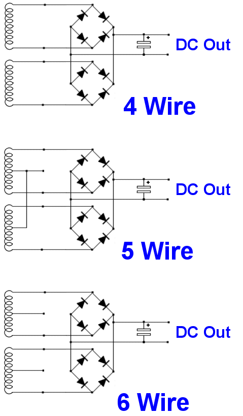 |
||||
| Bub73 Senior Member Joined: 10/12/2009 Location: United StatesPosts: 116 |
Can you post a photo of the schematic, also do you have and know how to use a DVM digital volt/ohm meter? |
||||
| Bub73 Senior Member Joined: 10/12/2009 Location: United StatesPosts: 116 |
click the little green arrow in the Post Reply box to upload images here. You may have resize/scale them so it will upload . Its late here and my battery's are getting low; I'll check back tomorrow. Bob |
||||
| Downwind Guru Joined: 09/09/2009 Location: AustraliaPosts: 2333 |
mygatt3 As Bob said your photos didnt load. If you still have trouble posting the photos than ask and we will give more help. Pete. Sometimes it just works |
||||
| mygatt3 Newbie Joined: 02/03/2010 Location: Posts: 13 |
sorry about that guys, and yes i do know how to use a multi meter for the most part |
||||
| Downwind Guru Joined: 09/09/2009 Location: AustraliaPosts: 2333 |
Ok the schematics is a bit useless to you in many ways as you do have what i think is a 3 phase motor. Do a ohms test between each wire or the solder dots on the back of the motor and you should find 3 wires about the same ohm reading this will a low ohm reading. This should tell you which is the 3 phase wires. Unless it is 2 sets of coils then you will get a reading between 2 wires for 1 coil and a reading between the other 2 wires for the other coil and nothing if you have a wire from each coil. Give it a go and let us know what you find. Pete. Sometimes it just works |
||||
| mygatt3 Newbie Joined: 02/03/2010 Location: Posts: 13 |
So i should put the two ends of the multimeter on two of the solder dots and see the reading and then move one of them to another dot while keeping the other on the same one and so on? And i will do this tomorrow i do not have access to a multimeter until the morning.. Thanks again Pete, sorry for all of the basic questions |
||||
| Downwind Guru Joined: 09/09/2009 Location: AustraliaPosts: 2333 |
By the way i think you will be lucky to charge a battery and might manage to power a led. Still a fun project all the same and a lot to be learnt from it. If you use a fan for the wind expect less than reasonable results as the air stream off a fan is very turbulent and effects the way the blades proform. Pete. Sometimes it just works |
||||
| Downwind Guru Joined: 09/09/2009 Location: AustraliaPosts: 2333 |
Yes you are correct with the multimeter Is a process of elimination. If it has 2 coils then the 4 wire schematic is what you will need to use. If it is a 3 phase motor then you will have 3 wires and forget about the other wire. Each of the 3 phase wires will go to a pair of diodes and in the case of using the bridge rectifiers you will connect a single phase wire to 1 AC terminal on the bridge and the 2nd phase wire to the other ac terminal and the 3rd phase wire to a ac terminal on the 2nd bridge. 1/2 of the second bridge will be unused. Then connect the 2 (+) of both bridges together and the 2 (-) of both bridges together. Now you should have DC output from your bridges (+) and (-) Connect your multimeter to the DC terminals and spin the motor you should get a reading. The higher the speed the greater the volts. If you short the DC wires together you should feel some greater resistance it turning the motor (you wont hurt it).....The greater the load across the DC output the greater the resistance to turn the motor. Hope it helps. Let us know how you get on. Pete. Sometimes it just works |
||||
| Downwind Guru Joined: 09/09/2009 Location: AustraliaPosts: 2333 |
A quick check of resistance on a hdd motor lying on the bench here gave me around 4 ohms on 3 of the 4 terminals and 2.5 ohms on the 4th terminal to any of the 3 others, so i would say this is a 3 phase motor with the 4th terminal being the star connection. You would use the 3 x 4ohm terminals and forget about the star terminal.(2.5 0hm) Wire it as i said above for a 3 phase motor. Pete. Ps. did you keep the magnets from the hdd you dismantled as they are a powerful magnet...Great for fridge magnets except they will pull the door off the fridge when you go to remove them  Sometimes it just works |
||||
| mygatt3 Newbie Joined: 02/03/2010 Location: Posts: 13 |
Thank you for the clarification. I will try to put it all together tomorrow on a bread board and see how it works. should I use the Bridge Rectifiers I have or should i get diodes? And yes I do still have the magnets from the hard disk drive. lol I plan to use them and some other parts to make a windbelt generator as well. Thanks again ill keep you posted on the progress |
||||
| Downwind Guru Joined: 09/09/2009 Location: AustraliaPosts: 2333 |
Use the bridges now you have them, but they will be big and bulky. Get it working with what you have and you can always refine it later if you want. Smaller diodes wont make it work any better, just look a little neater. I dont know what you are going to breadboard as there is only the bridges to connect till you get some voltage readings under good wind conditions. For an idea of what voltage you might get a different wind speeds check out the thread on cellphone charger as i done some testing there with a fan out of a computer power supply which is very simiular to the hhd motor. I would expect the bigger blades on your generator will spin slower and your voltage will be lower in the same wind speeds. Have fun!! Pete. Ps. recharging cellphone is in "Other Stuff" about 6 down the list. Sometimes it just works |
||||
| mygatt3 Newbie Joined: 02/03/2010 Location: Posts: 13 |
Good to know i can use what i have. once i get it connected ill let u know what i get out for voltage. I will be testing it with a fan seeing as i found out today that is how we will be testing them. Which isnt realistic but hey. (we will have a fan pointed at our prototypes for about 5 minutes and whichever can power a led the longest from a battery after that five minutes of charging wins lol) other constraints: must be no larger that 2 feet tall and 4 cubic feet Good news is that it spins very fast with fan and the blade i made isnt balanced yet. Once i get it hooked up i may hook up a capacitor to smooth out voltage and avoid the 'ripple effect'... What would you recommend for battery? I know it depends on what this things puts out but any ideas on whats most effective/efficient? Matt |
||||
| Bub73 Senior Member Joined: 10/12/2009 Location: United StatesPosts: 116 |
Here is a photo of a simple test board I put together for testing some of these little motors. Just hook your volt meter to the + an - select your wires and give it a spin the voltage you get for output will determine what battery size it may charge. Bob 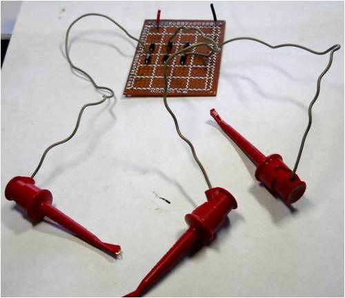

|
||||
| Downwind Guru Joined: 09/09/2009 Location: AustraliaPosts: 2333 |
Hi Matt, What is the purpose for the battery? You should be able to power a led direct without a cap or anything else other then the rectifiers. A cap wont hurt if you care to add one. The test sounds a little flawed if you just need to power 1 led. It dont prove very much except you can make 2 volts or more. Is this a in school project or state challenge. I would think you will need atleast 1.4 volts per cell for a AA nicad battery and most likely 2 AA cells to get enough voltage to power a led. So as i said lets wait and see what output you get. If you can test the current (amps) using your resistor and the multimeter as well would be handy to know. Also with the resistor connected between the (+) & (-) what voltage do you get with the meter across the resistor. Pete. Sometimes it just works |
||||
| Bub73 Senior Member Joined: 10/12/2009 Location: United StatesPosts: 116 |
Pete is right; one led for everybody's generator and battery combination makes no sense. Some of these motors may output more than others. If you where lucky enough to charge more than 2 AA's it may well let the magic smoke out of the led's; if a resistor of to high a value is serried with the led it may not light at 2 volts. Check an see if there are any battery size/voltage limits etc for this Project. Bob |
||||
| Page 1 of 3 |
|||||
| The Back Shed's forum code is written, and hosted, in Australia. | © JAQ Software 2026 |
