
|
|
Forum Index : Microcontroller and PC projects : Problem with PIC32MX470F512L
| Page 1 of 2 |
|||||
| Author | Message | ||||
| Frank N. Furter Guru Joined: 28/05/2012 Location: GermanyPosts: 1102 |
Hi, I have problems to program my PIC32MX470F512L with my original PicKit3. I soldered my PIC on this PCB: LINK I get always this error message from MPLAB IPE v2.20: "Target detected Unable to connect to the target device. Failed to get Device ID" I powered the PIC over my PicKit3 with "Power Target Circuit from Tool". My PicKit3 clone on my PC at home says that there would be a power problem and the measured voltage would be only 3V - but I think this could be a problem with my clone... I changed VCAP and I halved the serial resistors to 50R (R3/R4) on the PGC and PGD lines - no effect!!! Any ideas? Can anybody help me??? Thanks!!! Frank |
||||
Grogster Admin Group Joined: 31/12/2012 Location: New ZealandPosts: 9975 |
I never power the circuit from the PK3. Use a regulated external 3v3 PSU to power the circuit. Does your board have the 100n decoupling caps on each of the power supply pins? I've never bothered with any resistors on PGD or PGC - I just connect direct to the PK3 device. Smoke makes things work. When the smoke gets out, it stops! |
||||
| JohnS Guru Joined: 18/11/2011 Location: United KingdomPosts: 4335 |
+1 I've also had trouble powering from PK3 and no longer do it. Let us know if this fixes it or not please. John |
||||
| Frank N. Furter Guru Joined: 28/05/2012 Location: GermanyPosts: 1102 |
Hi, I had never before problems with powering over PicKit. I have 100n decoupling caps on the power supply pins, but programming in the past works very fine without them. I used now the power from my battery-powered MX170 Micromite board with my OLED - the result was that the power of my batteries are breaked down, my MX170 Micromite has lost his program and my OLED is now damaged!  I don't know why! I don't know why!
My OLED has now a weak lightning column after reprogramming of my MX170 Micromite... I think this f***ing MX470 is simple defect, but I don't know why! - It was a brandnew sample from Microchip. I can't measure any exeptional with my multimeter on the Vcc/GND pins. All seems to be ok and I handled it always EMC-compatible... Frank |
||||
bigmik Guru Joined: 20/06/2011 Location: AustraliaPosts: 2981 |
Hi Frank, Sorry to hear you may have a mini disaster on your hands. Re. Powering the chip with the PK3.... I have never been able to programme a 150/170 with my PK3 supplying power. When I did my NanoMite board I was able to programme the very first one I built using the PK3 but no more.. even with basically just a '170 SSOP chip and basic support components I cannot successfully use the PK3 to power it.. I always have to supply external power. I know this wont help with your `meltdown' but I wish you Good Luck with debugging what went wrong Regards, Mick Mick's uMite Stuff can be found >>> HERE (Kindly hosted by Dontronics) <<< |
||||
| Grogster Admin Group Joined: 31/12/2012 Location: New ZealandPosts: 9975 |
I would be wanting to measure the current flowing in your circuit at this point, as you power the circuit, and attempt to program it. I suspect there is some kind of fault current flowing somewhere. Programming a PIC - even on batteries, should not be a problem at all. Talking about the 170 specifically, at it's default running speed of 40MHz or so, the current consumption of it should be in the area of 25mA or so(give or take). It sounds to me like there is more current then this flowing somewhere. Is anything hot to the touch? EDIT: Are you able to post a photo of how you have things wired up? Perhaps we can see an error of some kind. ANOTHER EDIT: Check that your Vcap really is connected correctly. I had an issue a while back, that took a lot of fault-finding, and was causing the programmer to do all sorts of odd things. I had forgotten to ground the Vcap on the PCB, so although the Vcap was there on the board, it was electrically disconnected from ground. The PIC was doing all sorts of odd things during programming attempts. Even with Vcap disconnect like that, the IPE was still seeing the chip, and attempting to program it, then it would fall over with invalid memory reports, and general failure reports etc. Be very sure your Vcap is of the right size and type, and is definetly ground-referenced!  Smoke makes things work. When the smoke gets out, it stops! |
||||
| robert.rozee Guru Joined: 31/12/2012 Location: New ZealandPosts: 2528 |
likewise, i am sorry to hear you are having problems. not wishing to stir things up, but i have always had 100% success programming quite a number of MX150 and MX170 devices with a PicKit3 clone and: mplab 8.92, mplab X, and (with PK2 firmware) using pic32prog. i always use the PicKit3 to power the device - i never use external power. having said this, i use a dedicated programming jig that contains just the circuitry outlined in the micromite manual provided by geoff. if programming a device in-situ, one needs to make sure that any auxiliary circuitry does not interfere. from your description, and anecdotal evidence from the microchip forums, might i suggest you consider the possibility that your PicKit3 is faulty? is it a microchip genuine or a clone? my advice is to get a PicKit2 clone and use pic32prog - assuming it supports the MX470. if it does not yet, i (or G8JCF) can look at creating a compile for you that does. i am set up here to recompile pic32prog with ease, just a pity my C programming skills are so naff. cheers, rob :-) |
||||
| JohnS Guru Joined: 18/11/2011 Location: United KingdomPosts: 4335 |
Ouch - any dead chip sucks! If you have an RPi or an FTDI FT232 board (or even usbasps) you can try reflashing any of the cpus using the various programs I've posted, and a resistor network so not much chance of damage. No need for a Pickit at all. They all go via 2-wire ICSP and should recover any cpu that is upset but not if fubar'ed. The PIC32MX470F512H & L are both supported, as are MX170 and so on. John |
||||
| matherp Guru Joined: 11/12/2012 Location: United KingdomPosts: 11499 |
Sorry if this is too obvious to mention but use pins as follows: 100-pin MCLR 13 PGD 27 PGC 26 64-pin MCLR 7 PGD 16 PGC 15 and of course if you are powering from the Pickit set the voltage to 3.3V BEFORE turning on the Pickit power output |
||||
| Frank N. Furter Guru Joined: 28/05/2012 Location: GermanyPosts: 1102 |
Hi, here is my problem child! 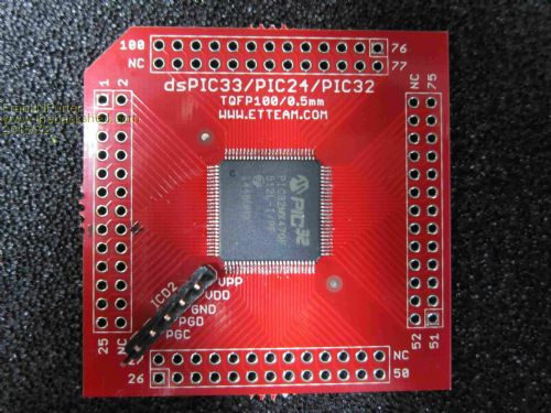
I can't find any mistake - I didn't use the John's Raspberry software (not yet - no time  ) )
I soldered 50R on R3 and R4 (PGC/PGD on 26 and 27). C8 is the VCAP and is the same capacitor as on my 32MX170 (which works with this PIC very well) I measured a resistance between all pin's in megaohms!? All solder joints are looking good under my microscope... Original AND clone PK3 doesn't find the chip... 
Many thanks to all for the help! ...but what's going on??? Frank |
||||
| matherp Guru Joined: 11/12/2012 Location: United KingdomPosts: 11499 |
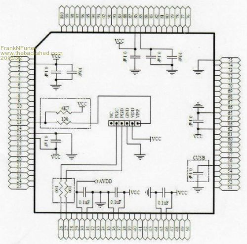
Compare the connections with the Colour Maximite circuit diagram. I would expect pins 2, 16, 37, 46, 62, 86, AVDD (30) and VUSB (55) to all be connected to VDD. Pins 15,31 36, 45, 65, 75 all to GND. The chip definitely won't run or program with AVDD unconnected (I've proved this!) |
||||
| WhiteWizzard Guru Joined: 05/04/2013 Location: United KingdomPosts: 2991 |
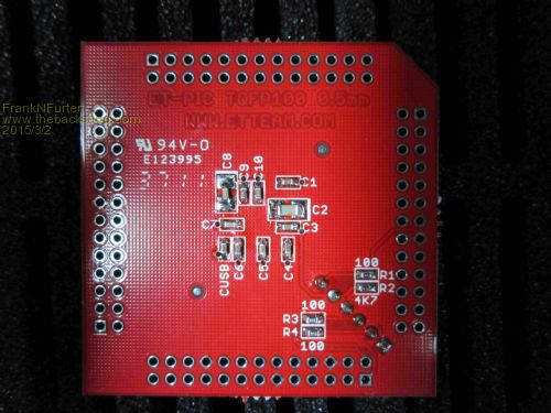
Hi Frank, I used one of these exact same BoB PCBs for my first homebrew MaxiMites. From memory, I had to make some (if not all) the power connections on the 'external' PCB that I plugged this module into. Looking at your photo's; how are you applying power to the MPU pins?? 
I now use different BoBs which have all the MPU's power pins connected to save having to do this 'externally'. And as MatherP says, ensure AVDD is connected too as these are not connected to anything on the BoB. Good luck . . . . PS I'm sure you have checked already, but do check continuity between ICSP pins and their destination to ensure no breaks. |
||||
| WhiteWizzard Guru Joined: 05/04/2013 Location: United KingdomPosts: 2991 |
Hi again Frank, Just dug out the MaxiMite on this particular BoB and done a quick continuity check. My memory failed me - this BoB does have the MPU's power pins connected to the ICSP but NOT the AVDD which as MatherP says, it must be connected too to Vdd. Hopefully solves your issue . . . |
||||
| Frank N. Furter Guru Joined: 28/05/2012 Location: GermanyPosts: 1102 |
Hi Phil, hi peter, many thanks to your response! I checked all connections: 2, 16, 37, 46, 62, 86 are all on Vcc 15,31 36, 45, 65, 75 are all to GND I soldered a bridge from Vcc to AVDD (30) and VUSB (55): "Unable to connect to the target device. Failed to get Device ID" 
Thanks again Frank |
||||
| matherp Guru Joined: 11/12/2012 Location: United KingdomPosts: 11499 |
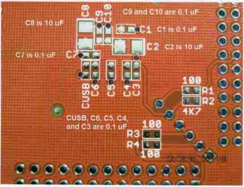
Frank You have got R1 and R2 in place and the correct values? |
||||
| WhiteWizzard Guru Joined: 05/04/2013 Location: United KingdomPosts: 2991 |
Have you tried powering from an external psu yet (just to eliminate PicKit3 powering issue)? |
||||
| Frank N. Furter Guru Joined: 28/05/2012 Location: GermanyPosts: 1102 |
Peter, you are my hero!!! 
What a stupid mistake! R1 was a 4k7 instead 100R! 
Now I can flash the device without any error with power from my PicKit! 
Many thanks to all for your help!!! ...next step is to connect the MX470 to my serial port... Frank |
||||
| JohnS Guru Joined: 18/11/2011 Location: United KingdomPosts: 4335 |
Hooray - great to hear it's fixed! But... did it really damage other things? How? John |
||||
| Frank N. Furter Guru Joined: 28/05/2012 Location: GermanyPosts: 1102 |
Hi John, with the benefit of hindsight I think it was my batterypack. It consists of two NiMH accus and a step-up controller to 5V. On my pinboard is a 3.3V linear regulator for Vcc. The batterypack is connected over a USB-cable with my board - and it seems that this connection has a loose contact!
I think that this connection/disconnection/connection has produced a voltage spike which killed my OLED. I have lost again my MX170 basic program after a short disconnection of my batterypack WITHOUT my MX470 connected and without a connected PC on my USB-serial converter... Frank |
||||
| JohnS Guru Joined: 18/11/2011 Location: United KingdomPosts: 4335 |
Ohhh, that could be it. What a nightmare. I was really puzzled because I mistreated PIC32 chips quite a bit during trying to figure the timings of programming out and never had any problem other than an incorrectly programmed chip. John |
||||
| Page 1 of 2 |
|||||
| The Back Shed's forum code is written, and hosted, in Australia. | © JAQ Software 2026 |
