
|
|
Forum Index : Microcontroller and PC projects : MM2: General purpose instrumentation PCB
| Page 1 of 2 |
|||||
| Author | Message | ||||
| matherp Guru Joined: 11/12/2012 Location: United KingdomPosts: 11604 |
Having got gauges working nicely the next step is to design a PCB that can connect directly to the TFT display and has a flexible I/O capability 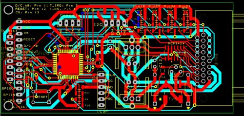
2015-06-03_103225_Instrument_-_PCB.pdf 2015-06-03_103358_Instrument_Schematic.pdf The idea is that the PCB will attach directly to either an ILI9341 or ILI9163 with them mounted vertically facing away from the PCB and centered on the PCB. This will allow the complete unit to be suitable for panel mounting in an appropriate enclosure. There is a single 26-pin DSUB connector (the next bigger version of the VGA DSUB) which is used to power the board and to bring all of the I/O ports out. The connector supports: 4 x 18-bit ADC channels with 8x programmable preamp, these can be used to measure directly thermocouples or strain gauges 4 x general purpose analogue/digital I/O ports with optional pullups, pulldowns, RC filters and GND and VCC connections. These can be used for DS18B20, thermistors, light sensors etc. 1 x port to support external IR 1 * relay/warning light drive circuit In addition the PCB has a I2C header with the correct pin mapping for directly mounting vertically a DS3231 real-time clock module or an EEPROM (or other I2c device) on a daughter board. The LED pin on the TFT can be connected via a shorting link directly to VCC or to the PWM2A port of the Micromite via a P-channel mosfet. A voltage divider and RC filter is provided to allow measurement of the incoming supply voltage using pin 19. The supply itself passes through a current limiting resistor, and diode to protect the circuit, in addition a bidirectional TVS is used after the resistor to remove any voltage spikes. The primary regulator will be a LM2940 which is specifically approved for vehicular applications. ISCP and Console ports are available on the PCB I'd appreciate any comments and ideas Peter |
||||
| WhiteWizzard Guru Joined: 05/04/2013 Location: United KingdomPosts: 2991 |
You trying to put Grogster out of a job??  |
||||
| viscomjim Guru Joined: 08/01/2014 Location: United StatesPosts: 925 |
This is nice. I am currently trying to come up with a nice "bezel" mounting type panel thing for the different displays that looks good and works good for non-touch and touch displays. The way they are made, makes it kind of difficult to design a "good" method to do this. Try googling tft lcd display bezel or similar and you will see that there is not too much out there. It would be nice to incorporate this in a few projects and actually make it look good and professional. If anyone has any ideas, bring them on. I have access to cnc routers and lasers so I can play around a bit. This would be the icing on the proverbial cake. |
||||
Grogster Admin Group Joined: 31/12/2012 Location: New ZealandPosts: 9985 |
Yeah, man, what's the big idea?????!!!!!   
Seriously, I like this design. Should be especially good for in-car use, which it would seem is what you have based the design on? What with the car-happy regulator etc... Nice one, matey, and I look forward to you putting up photos of the finished unit.  Smoke makes things work. When the smoke gets out, it stops! |
||||
| MicroBlocks Guru Joined: 12/05/2012 Location: ThailandPosts: 2209 |
I tried to read the schematics but i can not really find all the connections. A missing one is the MCLR. I can not find to what this is connected in the schematics. I can see it in the pcb layout but that is way to difficult to see if there are design issues. I know you know enough about electronics to not make obvious mistakes but it never hurts for a set of extra eyes to go over it. Might it be that not all net labels are shown in the schematic? Microblocks. Build with logic. |
||||
| matherp Guru Joined: 11/12/2012 Location: United KingdomPosts: 11604 |
Might it be that not all net labels are shown in the schematic?
TZ Designspark only labels wired connections if you ask it to. Connections where you just specify the net name are shown properly. I'll go though and label up some more of the wires. The only other one I can see at the moment is GND on the ICSP. Can you see any more? Net MCLR (pin18) does connect to pin 1 of the ICSP header but you are correct this can't be checked on the schematic. Thanks for looking, you are correct we can all make mistakes! Peter Edit new version 2015-06-03_162104_Instrument_Schematic.pdf |
||||
retepsnikrep Senior Member Joined: 31/12/2007 Location: United KingdomPosts: 134 |
As this is a design to interface with cars, and in the display demo had various engine parameters displayed, it needs to be able to talk to the car via the OBDII port or perhaps CAN. OBDII ISO 9141 is fairly straightforward idle high serial data, and I would suggest adding an open collector driver and an input potential divider to allow the pcb/pic to talk to an OBDII compliant vehicle on either of two lines. The standard ISO 9141 KLIne is a 12V bus running at 10400 baud. A additional option of another 5V bus. So two transistor drivers and two input circuits one 12v, and one 5v to allow the car to talk to the gizmo. This would use 4 I/O lines. Of course you could add a daughter board but all in one would be nice. Gen1 Honda Insights. |
||||
| matherp Guru Joined: 11/12/2012 Location: United KingdomPosts: 11604 |
NO!!!!!!! strictly aeroplanes |
||||
| WhiteWizzard Guru Joined: 05/04/2013 Location: United KingdomPosts: 2991 |
Peter - the link doesn't work and you've left us very curious! |
||||
BobD Guru Joined: 07/12/2011 Location: AustraliaPosts: 935 |
He posted it once before Phil. Here is the link for you now but I am surprised at the .com.AU part of it. http://www.tailwindbuild.blogspot.com.au/ However it works for me. Bob |
||||
| matherp Guru Joined: 11/12/2012 Location: United KingdomPosts: 11604 |
retepsnikrep Just re-read your post again and I think the circuit as-is can accommodate what you suggest. There is an open collector driver that I had nominally allocated to driving an external relay or warning light. Also the four general purpose I/O ports can be set up as potential dividers by populating the the board appropriately. If you look at I01 then the position C15 on the board just takes a standard 1206 SMT component. Using a resistor here and also in R19 gives a potential divider. With 4.7b8 Geoff has released Cfunctions to run serial i/o on any pin. If this is something you are interested in playing with let me know and I'll send you a PCB once they arrive from China. All Sorry about the aeroplane link "blogspot" does something funny with addresses. The base .com address seems to end up converted into something local depending on the country you are in. If you hover over my link rather than clicking on it you can see the address to use. |
||||
| WhiteWizzard Guru Joined: 05/04/2013 Location: United KingdomPosts: 2991 |
A flying car then! |
||||
Lou Senior Member Joined: 01/02/2014 Location: United StatesPosts: 229 |
Wiz, Do the new flying cars come OBDII equipped now ?? Peter, All I can say is triple WoW !!! You never cease to amaze me, all the neat stuff you do. I can't wait for Zonker to build one and show it to me, keep up the good work. Lou Microcontrollers - the other white meat |
||||
centrex Guru Joined: 13/11/2011 Location: AustraliaPosts: 320 |
Hi Matherp If you are getting a number of these boards made please put me on the list to purchase one. Having an i/o board to connect to one of the displays will make it come alive, not necessarily for an aircraft. Thanks for all the effort. Regards Cliff Cliff |
||||
| centrex Guru Joined: 13/11/2011 Location: AustraliaPosts: 320 |
Inspired by Matherp's io board but not having a 44 pin pic chip I had to use a 170 and a 2.8 touch lcd screen. The picture below is what I ended up with, it is based on Bigmicks BP170 with the added icsp as well as the ability to fit series resistors on the the remaining two analog ports, pullup resistors on the digital ports. All the inputs can have bypass caps fitted, it also has two voltage regulators so can run of 5 or 12 volts. The board is homebrew double sided but not plated through so it requires soldering on both sides as well as a few jumpers. Unfortunately it appears that Riston coated pcb material is no longer available here in Aus. 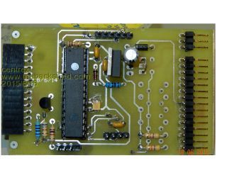
The tft screen plugs into the left hand socket the pins at right are power at the top with io pins underneath these pins also have ground and plus 3.3 volts on alternate pins. Regards Cliff Cliff |
||||
| matherp Guru Joined: 11/12/2012 Location: United KingdomPosts: 11604 |
My boards arrived yesterday so I've built one up to test. Of course for a production environment the display and the RTC would be soldered direct rather than socketed and the board would only be populated to the extent required. 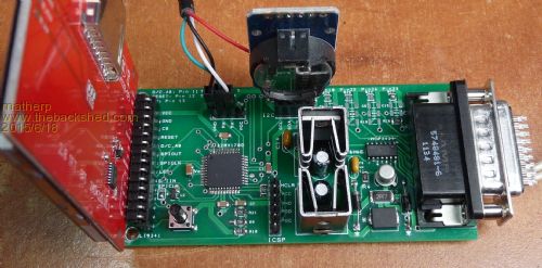
Everything seems to work well with the ILI9341 or 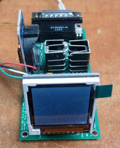
ILI9163. There are a couple of changes I need to make for version 2. First I should have had a decoupling capacitor across the power pins of the MCP3424 ADC. Second, the silkscreening for the diodes is the wrong way round (thanks RS!). In addition I've added a header for an openlog to the layout. I'll continue to test and make changes to version 2 Update Unfortunately the PWM control of the backlight doesn't work. I knew it might be an issue as I am trying to turn off a p-channel mosfet connected to 5V with a gate at 3.3V - it stays on 
The next version will have to use a npn transistor to switch the mosfet 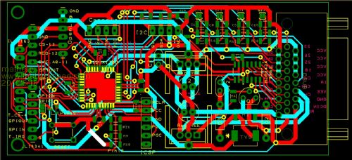
if required. If anyone wants one of the current version PCBs then send me a PM and and I'll pop one in the post. I have 8 spare. |
||||
TassyJim Guru Joined: 07/08/2011 Location: AustraliaPosts: 6543 |
Peter, This is the circuit I used with one of Micks BP170 boards. 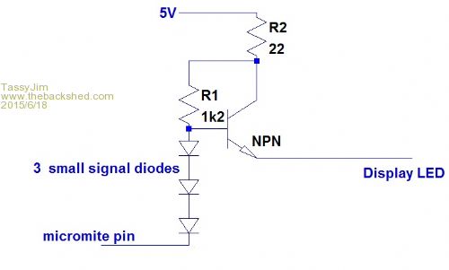
With the values shown, the maximum LED current was ~10mA. This was as bright as I wanted but I think the 22 ohm should be less and probably the 1.2k as well. I also think that 2 diodes would work without any risk to the micromite pin. I need to do a breadboard and run some more tests. I would also put the 22 ohm resistor after the transistor but the board layout didn't suit - but that might mean I do need the three diodes for switching ON. Jim VK7JH MMedit |
||||
bigmik Guru Joined: 20/06/2011 Location: AustraliaPosts: 2981 |
GDay Cliff, All, Whilst Riston is not available any more in Aus... ALTRONICS.COM.AU stock pre coated positive resist (I think Riston was positive resist) blank boards. See these for Double sided, Prices seem reasonable.. 114mm x 165mm 150mm x 300mm Altronics have dealers in most states.. Also ACETRONICS.COM.AU advertise them but you have to contact them for pricing. Acetronics Regards, Mick Mick's uMite Stuff can be found >>> HERE (Kindly hosted by Dontronics) <<< |
||||
Bryan1 Guru Joined: 22/02/2006 Location: AustraliaPosts: 2137 |
G'day Guy's, Kalex also do the Kinsten positive acting boards at pretty good prices too. Cheers Bryan |
||||
| SteveP Newbie Joined: 21/03/2013 Location: United StatesPosts: 19 |
An optically isolated solid state relay might be used for the backlight PWM. The CPC1002 is less expensive than most because its output has polarity. 2 mA will turn it on and it can be used as a high side switch to source current or low side switch to sink. It acts like a light activated resistor that changes from high to low resistance when it's isolated input led is turned on. Steve |
||||
| Page 1 of 2 |
|||||
| The Back Shed's forum code is written, and hosted, in Australia. | © JAQ Software 2026 |
