
|
|
Forum Index : Microcontroller and PC projects : MicroMite controlled 4-CH stereo...
| Page 1 of 8 |
|||||
| Author | Message | ||||
Grogster Admin Group Joined: 31/12/2012 Location: New ZealandPosts: 9973 |
My main HT amp died at the weekend, and although I could spend time trying to fix it, I think the problem is in the logic board, and that is really new amp time, unless you can find another logic board.... 
So the thought occurred to me: "Why not see if I can make my own one using a MM for the controller?" It won't be HDMI capable, but C'est La Vie. The object is to make it reasonably cheap, so many others could copy it if they wanted. The idea at this stage is to connect a MicroMite(probably the 28 pin one), SPI LCD with touch and a TDA7419 audio processor chip to make a small, cheap stereo system pre-amp with LCD display and control. The TDA7419 is a 3-band stereo audio controller designed mainly for car-stereo applications, but it is cheap - only US$7 from Mouser - has up to four stereo inputs, bass, middle and treble controls, loudness and subwoofer output, direct mute and soft-mute and four separate line outputs for driving up to four speakers in a front/rear arrangement - final audio configuration would be 4.1 The device is controlled via I2C, so I figured this would be a useful way for me to play with the touch controls of the latest MM firmwares, practise my I2C and also produce something many could perhaps use practically in their daily lives. There are lots of cheap class-D amplifier modules on eBay of various impressive output powers for the price, that this unit could then connect to, producing a relatively small but powerful amplifier for analogue audio applications. The initial concept is to produce the board and controller as a pre-amp, with the four line-level outputs + a subwoofer output, and the constructor would then pair this board up with amplifiers to suit their needs. This has the advantage of keeping the price tag low - you pick amps that suit your budget, rather then be locked into a certain amplifier configuration. Not sure if this is gonna be of much REAL interest here, but I post the thread in the hope that other members may be interested in this idea, and can follow along as I develop the concept. I fully expect to have some I2C issues, as I am still learning I2C to some extent, but hopefully they will be minimal. Initial PCB layout is under way, and I will post an image here tonight(my time). It will be a 100x100 PCB, which you can get ten of from ShenZhen2U for US$12. Do we have any interest? Smoke makes things work. When the smoke gets out, it stops! |
||||
OA47 Guru Joined: 11/04/2012 Location: AustraliaPosts: 1050 |
Sounds like the Grog's cogs have started whirring  Looking forward to the next episode.. Have you thought about implementing the IR for additional control? Looking forward to the next episode.. Have you thought about implementing the IR for additional control?
Keep them coming Grogster GM |
||||
| Grogster Admin Group Joined: 31/12/2012 Location: New ZealandPosts: 9973 |
Hey there - yes, IR via the MM's commands, reflected on the LCD. Have not had a chance to play with the IR commands with any kind of seriousness, so that is on the pile too.  Smoke makes things work. When the smoke gets out, it stops! |
||||
| viscomjim Guru Joined: 08/01/2014 Location: United StatesPosts: 925 |
Grogster, this is very interesting. I will definitely be following this one! |
||||
| Grogster Admin Group Joined: 31/12/2012 Location: New ZealandPosts: 9973 |
Initial PCB done. There are still some tweaks to do. It is 100x75. TOP(LCD side): 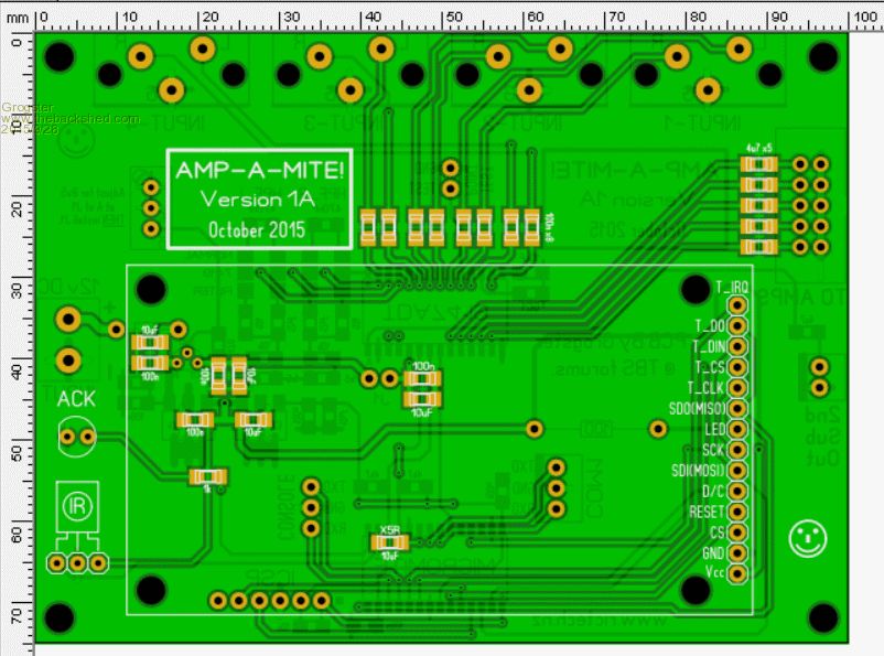
BOTTOM: 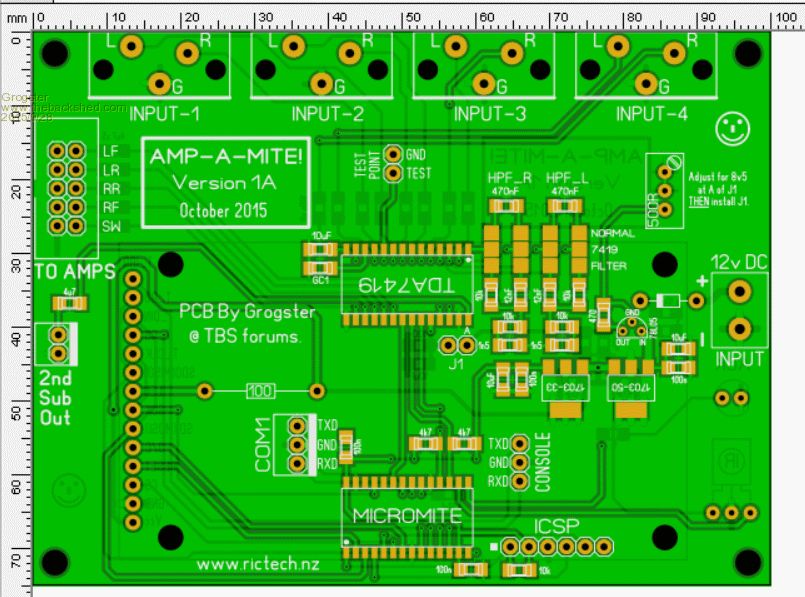
I have never used the 7419 before, so I just copied the datasheet test circuit for the 1A board, so I can tinker. Inputs 1-4 are via dual-RCA sockets mounted on the board. As everything to do with the audio side of things is done through I2C commands, I should be able to test out everything using test loops in the MM for a start, then once I get the hang of everything, I can write some proper code incorporating the LCD. Smoke makes things work. When the smoke gets out, it stops! |
||||
| viscomjim Guru Joined: 08/01/2014 Location: United StatesPosts: 925 |
Grogster, are you going to implement or at least be able to implement the spectrum analyzer? This could make for a cool display and other things... This is a very cool chip. |
||||
| Grogster Admin Group Joined: 31/12/2012 Location: New ZealandPosts: 9973 |
Yes, I have the Spectrum Analyser pins will be connected to the MM, but that will be one of the latter things I play with on the code side of things. You clock the chip from the MM and it responds with analog voltages representing the current state of the 7-band equalizer - quite clever, and simple analog voltages are nice and easy to read by the MM chip. So, yes - I am going to assign an analog pin to this. 
I looked at several TDA chips before settling on this one. Cost was one factor, but not the only one. This chip has the best balance of features vs cost, IMHO, based on the research I did. No doubt other members know of other(perhaps better?) processor chips, but this is the one I decided to use in any event. Any chip I chose had to have a sub output, as these days, this is pretty much standard and expected.(to have a sub channel). It also allows use of much smaller main speakers. Smoke makes things work. When the smoke gets out, it stops! |
||||
| viscomjim Guru Joined: 08/01/2014 Location: United StatesPosts: 925 |
Another cool feature is the MIX input that I am assuming is used for either a gps or cellphone input as it is routed to the left and right front speakers. I'm starting to like this chip and the fact that the uMite will be it's master, should be pretty cool what comes from this. |
||||
| Zonker Guru Joined: 18/08/2012 Location: United StatesPosts: 772 |
GO GROG's.. Awesome project...! I never thought of audio process controller stuff... And Yikes..! PCB on the table... Nice...
|
||||
| OA47 Guru Joined: 11/04/2012 Location: AustraliaPosts: 1050 |
Grogs, Have you thought of how you are going to house the PCB/Display? My first thoughts were for a 2RU panel so the LCD would have to be at right angle to the PCB. Just a thought GM |
||||
| Grogster Admin Group Joined: 31/12/2012 Location: New ZealandPosts: 9973 |
@ Jim - I am using the MIX pin as a 2nd sub out at this stage, but you can configure that pin to be an input if you like, all via I2C. When used as a mixer input, it would seem that you can feed audio in here, and mix it to the FRONT set of speaker(but not the rear) all under I2C control. The PCB could cater for either or - just change the 4u7 cap for a 100n to make '2nd Sub Out' into the MIX input.
...hopefully you all have noted that I have designed this board so that either 1206 or 0805 SMD passives can be used throughout... 
@ Zonker - Audio has always been a passion of mine, and now that the MM has so many features and the touch-screen support, the MM is just begging to be used as some form of audio controller.  Smoke makes things work. When the smoke gets out, it stops! |
||||
| Grogster Admin Group Joined: 31/12/2012 Location: New ZealandPosts: 9973 |
@ Graham Meager - 2U 19" rack case panel is 88mm high, so with the board being 75mm, you have 13mm either side, so 6.5mm clearance top and bottom in a 2U case. It would fit, if that's the case you were thinking of, and will probably be the way I will do it too. I will probably shave a few more mm off the board size yet, which will make it even smaller. I might also use vertically mounted PCB RCA's too, which would make it even neater. You can always mount the LCD seperate from the mainboard, which would allow you to squeeze the LCD into a 1U case if you wanted to. Smoke makes things work. When the smoke gets out, it stops! |
||||
| OA47 Guru Joined: 11/04/2012 Location: AustraliaPosts: 1050 |
I know its thinking ahead a bit far but on the subject of enclosure do you have any thoughts on a surround for the LCD to finish it off as you will need access to the touch screen but be able to hide the surrounds? Will you think of a power supply for the module? If so power on via power switch or by touchscreen? Or could the main amp supply power via HDMI or USB? I see that you have 12V in, is this needed for the audio chip? GM |
||||
| Grogster Admin Group Joined: 31/12/2012 Location: New ZealandPosts: 9973 |
Hey.
I am rehashing things a little now to make the board smaller, so it WILL fit in a 2U case, with plenty of spare room. I am moving the RCA input sockets to a seperate sub-board, which is still part of a 100x100 panel. As to surrounds, no, I have not thought that far ahead - you are right.
PSU will most likely be any one of many of those switch-mode supplied you can buy for enclosed equipment. These can be had in quite juicy form(8 amps or more) and are quite affordable. The main amp module I am going to use for the prototype uses one of these @ 32v. There will be a pre-regulator arrangement(buck converter) to drop the 32v to 12 or 13 volts for the main preamp board here. As the 7419 seems to want to settle on an 8.5v supply voltage, I elected to use a 78L05 5v regulator and 'Jack up' the output voltage by re-convincing the 78L05 as to where it's ground reference was. This is a very common move for changing fixed regulators above their set voltage.
The 7419 wants a supply between 8v and 10v - not much room to move. 8v is minimum, 10v is maximum. I could use a 7809 or similar I suppose, but all the data in the PDF seems to be done at 8.5v, and that is the nominal supply, so that is what I am designing it to run on. LCD display LED backlight and IR receiver are on regulated 5v, and the MM and LCD controller are on regulated 3v3. EDIT: I think I will just run the 7419 on 9v and be done with it. 9v is smack in the middle of the 8-10 volt supply range, and only 500mV higher then the 8.5v nominal figure anyway, and 8.5v nominal probably means closer to 9v anyway... Smoke makes things work. When the smoke gets out, it stops! |
||||
| OA47 Guru Joined: 11/04/2012 Location: AustraliaPosts: 1050 |
Grogs, I have posted before regarding using 8mm styrene T section to make a frame for the displays: Forum Post May 2015 This is the only answer I have been able to come up with. GM |
||||
| Grogster Admin Group Joined: 31/12/2012 Location: New ZealandPosts: 9973 |
One way around this issue is to have a custom-made case. They are not as horribly expensive as you think, when you consider the price of a 19" rack case. Laser-cut steel that is then powder-coated, or a laser-cut perspex plastic case that is then plastic-welded is also a nice option - have not got that far yet, but that will come if the circuit comes together OK! Smoke makes things work. When the smoke gets out, it stops! |
||||
| Grogster Admin Group Joined: 31/12/2012 Location: New ZealandPosts: 9973 |
UPDATE Board is 10mm smaller now - 100x65, so will definitely fit in a 2U case now, and the audio inputs are now on a IDC cable same as the audio outputs. For line-level signals, IDC is fine, and in fact, if you look inside many a commercial amplifier, this is exactly how they couple their audio from board to board - via FPC cable or other flat multi-core. ...you can't do this with low-voltage inputs(Phono/Record-player cartridge or dynamic microphone), but this unit does not allow for that anyway... The same 100x100 panel will now contain a 2nd board, which will be the input panel. The input panel is linked to the main preamp board with 16-way IDC cable and plugs. The signals are laid out as signal/ground/signal/ground, to minimize any crosstalk and to also allow nice easy connection by either IDC cables, or even just plain old jumper wires if need be. The I2C bus and 5v supply are now also on a header, as I have plans for a 3rd board specific to my needs, which will be another MM controlled speaker A/B switching arrangement plus speaker de-thump relays. TOP: 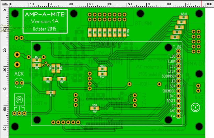
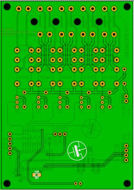
BOTTOM: 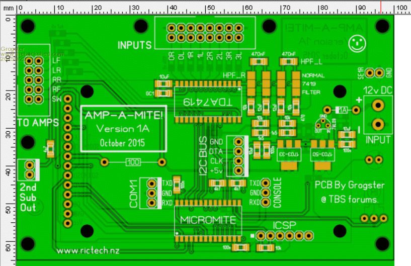
...the tinkering continues... Smoke makes things work. When the smoke gets out, it stops! |
||||
| WhiteWizzard Guru Joined: 05/04/2013 Location: United KingdomPosts: 2977 |
Looking good there Grogs - got my eyes on this one
WW |
||||
| Grogster Admin Group Joined: 31/12/2012 Location: New ZealandPosts: 9973 |
UPDATE I have designed a speaker relay board, also controlled by a MM. This board serves a couple of functions: (1) speaker de-thump relays as all speakers are off by default, and (2) speaker switching and zone selector. All of these relays can be turned off and on via the main pre-amp's MM I2C Master and the GUI SWITCH controls, which allows for full control of which speaker sets you want on or off. At power-up, this board will enable all four speakers, the sub and select zone1 for the front speakers. 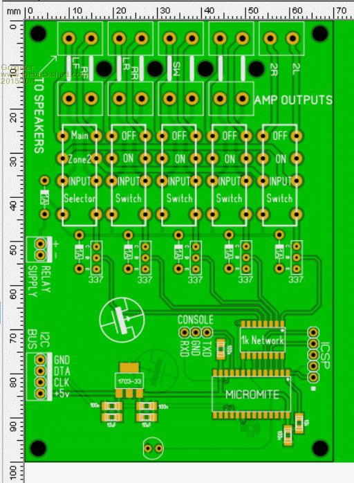
This board gets its power and I2C control from the main pre-amp board. The relays have their own supply line, as I have not decided on 5v or 12v relays yet - probably 12v ones as this will take the relay coil load off the 5v regulators. There are no pull-ups on the I2C bus on this board, as they are on the pre-amp board. ...i'm enjoying myself with this one, as audio and amplifiers are something I am into, so I can combine both my current interests at the moment... Smoke makes things work. When the smoke gets out, it stops! |
||||
TassyJim Guru Joined: 07/08/2011 Location: AustraliaPosts: 6533 |
It is something that I am watching closely. I have my amateur radios running within sound of the bedroom and lounge, and when I forget to turn them off at bedtime, the Boss gets annoyed with the late night sounds. On my to-do list is a volume control that I can control with the phone and an automatic night switch. Your module is spot on. Jim VK7JH MMedit |
||||
| Page 1 of 8 |
|||||
| The Back Shed's forum code is written, and hosted, in Australia. | © JAQ Software 2026 |
