
|
|
Forum Index : Microcontroller and PC projects : HELP needed with 2.4" TFT and MM+
| Page 1 of 2 |
|||||
| Author | Message | ||||
| WhiteWizzard Guru Joined: 05/04/2013 Location: United KingdomPosts: 2991 |
I am after some confirmation to see if I have a 'local' issue, or whether there is a wider compatibility issue with 2.4" TFT modules. IF you have a MM+ and a ILI9341 display (typically 2.4" or 2.8" like the one pictured in Geoff's manual) can you please try the following: (you will ideally need both a touch panel, and an SD card connected) 1> Try the LOAD IMAGE command to see if the image loads ok (or does it display 'staggered' pixels)? 2> Try the GUI TEST LCDPANEL command. Observe the circles and check to see they are all filled solidly (rather than the occasional one being filled with 'pixelated noise') I have built several units and none of them allow me to LOAD IMAGE. The odd pixelated circle can be eliminated if I remove the SD card AND the touch panel. It is as if the SPI bus is being 'overloaded' and I am trying to see if this is caused by the TFT module. By the way, I am using an 'external SD socket - NOT the one on the TFT module. Geoff has confirmed everything works on his setup so it is not a 'bug'. The more people that respond, the easier it will be for us to address. THANKS in advance . . . 
WW |
||||
| matherp Guru Joined: 11/12/2012 Location: United KingdomPosts: 11493 |
WW Works fine for me. Are you using the MM+ USB console? If so, please could you try using an external USB uart with the MM+ USB completely disconnected. |
||||
| MicroBlocks Guru Joined: 12/05/2012 Location: ThailandPosts: 2209 |
Can not test but it sound like the transition between low and high is not fast enough. Maybe adding a pullup resistor on the data line might help. Did you look at the signals on a scope? Microblocks. Build with logic. |
||||
| WhiteWizzard Guru Joined: 05/04/2013 Location: United KingdomPosts: 2991 |
Thanks guys . . . @matherp - I am using an external USB-to-TTL (as I always do by the way, simply because I need to keep the TT connection alive!) @MicroBlocks - I thought of that early this morning and emailed Geoff as to his thoughts. Even though SPI is driven high and low, additional pull-ups (or pulldowns?) may make all the difference. Will be trying this later. Please - any more folk out there with ILI9341 TFTs able to try the above? 
WW |
||||
| matherp Guru Joined: 11/12/2012 Location: United KingdomPosts: 11493 |
WW What pins are you using to drive the various chip selects? Is the ILI9341 set to 3.3V mode (J1 made) or 5V mode? You shouldn't need external resistors. I'm running on a breadboard with flying wires and this is the clock pulse I'm seeing - perfectly acceptable. 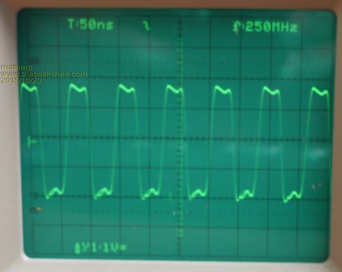
Sorry about the poor picture quality  |
||||
Grogster Admin Group Joined: 31/12/2012 Location: New ZealandPosts: 9975 |
I have 2.4" SPI on MM+ - test display command is fine. Do you have a test image for 2.4" I can try? EDIT: I reformatted a photo to 320x240 for this LCD, and loaded it. It loaded OK, but there are colour issues. This was not an issue on the parallel 1963 LCD's. 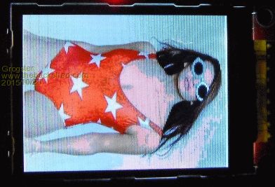
Sorry this image is not the best - neither is my camera. Note the pink discolouration around the face and lower neck. Not sure if this is what you are seeing or not. Also, the orange on the swimsuit is pixelated in two shades of orange - light and dark orange. This SPI LCD is fine with text and graphics. Smoke makes things work. When the smoke gets out, it stops! |
||||
| matherp Guru Joined: 11/12/2012 Location: United KingdomPosts: 11493 |
Remember on the SSD1963 you have full RGB888 resolution. On the ILI9341 you only have RGB565 i.e. there are only 32 red and blue levels and 64 green. This can create significant colour issues. |
||||
| Grogster Admin Group Joined: 31/12/2012 Location: New ZealandPosts: 9975 |
Ahhhhhhhhh - Yes, that would be it!  Good thinking. Good thinking.
Here is a better image, but as you say....... 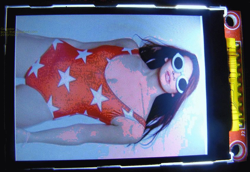
Colour issues aside, the image loads fine, is correctly aligned and not missing any lines or other artefacts. This is with a 2.4" SPI LCD on MM+ @ 100MHz - unless this has something to do with 120MHz? Smoke makes things work. When the smoke gets out, it stops! |
||||
| WhiteWizzard Guru Joined: 05/04/2013 Location: United KingdomPosts: 2991 |
Thanks Peter/Grogs, Just to be clear, all three SPI components work individually; and they all work when connected to the same SPI bus (as per manual). So the display is drawing lines, circles, text etc, and the touch panel works fine, and the SD card reads fine. Note that the previous issue of FILES fspec$ was an issue with 'missing' code from the firmware and this bug I can confirm has been squashed by Geoff. The 'pixelation' of the GUI TEST LCDPANEL results in random coloured/noisy pixels on the OCCASIONAL filled circle BUT ONLY when SD card AND Touch panel are connected to the SPI bus. When I remove the SD card from the socket AND disconnect touch, then no circles at all are pixelated. With either one connected, then I still get the odd 'noise' fill, but less circles filled like this than when both SPI devices are connected in. And the LOAD IMAGE just creates a 'staggered' pixel image across the whole screen; even when Touch and SD are disconnected. I appreciate the reduction in colours causing the effect in the above photos; this is not the type of pixelation I am referring to. But at least you get your image displayed unlike me
I have tried grounded/shielded cables between the SPI lines but no affect. Leads are no longer than 10 cm (using ribbon cable). Totally baffled by this at the moment hence why I want to see if anyone else can't get an image with the LOAD IMAGE command. I am not too concerned by the GUI TEST LCDPANEL issue, but as Geoff has hinted at, the two issues are probably linked. Have tested on two TFTs (from the same supplier), four PSUs, and two E64 modules as well as two of my own custom setups. Mystery continues . . . .  |
||||
| matherp Guru Joined: 11/12/2012 Location: United KingdomPosts: 11493 |
If 5V mode are you supplying 5V on pin 1 |
||||
| Grogster Admin Group Joined: 31/12/2012 Location: New ZealandPosts: 9975 |
My test LCD was a non-touch one. That might explain why my LCD was OK. I don't have an SPI LCD with touch hooked up to a MM+, but I could do this for testing purposes if you like. Smoke makes things work. When the smoke gets out, it stops! |
||||
| WhiteWizzard Guru Joined: 05/04/2013 Location: United KingdomPosts: 2991 |
Yes please
Two tests: 1> GUI TEST LCDPANEL (with touch panel connected, AND SD card inserted 2> LOAD IMAGE - does it still load ok? Thanks G |
||||
| matherp Guru Joined: 11/12/2012 Location: United KingdomPosts: 11493 |
WW My test was MM+ running on a modified Skinnymite, with all three controllers connected: display, touch, SD It works perfectly and the oscilloscope plot was on that configuration. Have you got access to a scope to have a look at your signals? |
||||
| Grogster Admin Group Joined: 31/12/2012 Location: New ZealandPosts: 9975 |
@ WW - matherp's post above suggests there should be no problems, but I will do a test tomorrow(my time) anyway - just for the Hell of it. Smoke makes things work. When the smoke gets out, it stops! |
||||
| WhiteWizzard Guru Joined: 05/04/2013 Location: United KingdomPosts: 2991 |
J1 is open circuit, 5v applied to Vcc (pin1?) HOWEVER, C2 is missing from the PCB (and looks like it has 'fallen' off as the pads have solder on them as if there was once something there. I guess this is a de-coupling cap for U1 (touch controller). I have had SMD components arrive loose before from our cheap friendly suppliers so it wouldn't surprise me if this is the cause of my issues. Any guidance as to value of C2 anyone? |
||||
| WhiteWizzard Guru Joined: 05/04/2013 Location: United KingdomPosts: 2991 |
Nope - just a logic analyser I'm afraid. Holding out hope that the lack of C2 is the cause of issues. May find a 0.1uF to drop in there . . . EDIT: A 0.1uF had no impact to what I am seeing |
||||
| WhiteWizzard Guru Joined: 05/04/2013 Location: United KingdomPosts: 2991 |
Photos of my two issues: 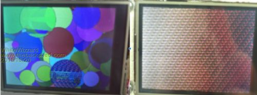
The left hand image shows a 'pixelated' filled circle (using GUI TEST LCDPANEL). This was quite hard to capture as it is only the 'occasional' circle that gets filled like this. Note that the pixels look consistently staggered, but there is 'noise' in the middle rows. Most of the time, the circles are filled with random coloured pixel noise rather than being 'patterned' like this one is. The right hand image is the effect I get whenever I use LOAD IMAGE. The file used was Geoff's Tiger2 image posted in another thread. It is a 320x240 bmp. Notice the repeating pixel pattern that fill the screen i.e. no 'noise' here. Once a Load Image is issued, control is passed back to the command prompt cursor; but if I then issue an SD command such as FILES, it returns with 0 directories, 0 files. If I reboot with WATCHDOG 1, then issuing a FILES command after the reboot causes the SD card not to respond at all (until timeout reached). So something is affecting the SPI lines. If anyone else gets this 'staggered pixel' effect on LOAD IMAGE then please let me know!
Thanks . . . . WW |
||||
| matherp Guru Joined: 11/12/2012 Location: United KingdomPosts: 11493 |
WW I think you have to be looking for a hardware fault. Can you post pics/circuits etc. of your environment. Check for shorts between pins: all the CS pins as well as the SPI pins, not just with themselves but with any other pins you have wired. Is this the same environment you are getting processor exceptions? Nobody else is reporting that problem either. All points to hardware as far as I can understand. |
||||
| Grogster Admin Group Joined: 31/12/2012 Location: New ZealandPosts: 9975 |
My results are fine. 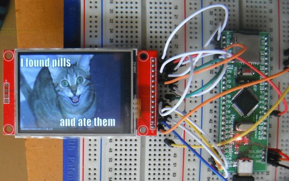
No artefacts in the GUI TEST DISPLAY demo either. Sorry - this is probably not what you wanted to hear, but......... Touch calibrated and working fine with the GUI TEST TOUCH command. I tried touching the screen while both GUI TEST DISPLAY and LOAD IMAGE were in progress - not a sausage of the problem you are seeing. Not much help, I realise. 
EDIT: Here is a link to my kitty-cat image. See if you can load that at your end. Smoke makes things work. When the smoke gets out, it stops! |
||||
| WhiteWizzard Guru Joined: 05/04/2013 Location: United KingdomPosts: 2991 |
Thanks Grogs for testing that. I will have to wait until the next lot of ILI9341's arrive before I think this matter will be resolved. It has to be the display as everything else has been tested and retested. As I mentioned to Geoff, I just hope this is not another repeat of the Distance Module scenario where initially some people's worked, and others didn't i.e. the source of the 'not-quite-standard' module impacted you outcome. Thanks again to all those that have posted here with your results. PS I will try your cat image shortly just in case my TFT doesn't like Geoff's Tiger!!
WW |
||||
| Page 1 of 2 |
|||||
| The Back Shed's forum code is written, and hosted, in Australia. | © JAQ Software 2026 |
