
|
|
Forum Index : Microcontroller and PC projects : MM+ school laptop
| Page 1 of 6 |
|||||
| Author | Message | ||||
kiiid Guru Joined: 11/05/2013 Location: United KingdomPosts: 671 |
Geoff and Peter Mather in their combined work have created a perfect environment for learners, and even not only, however so far there hasn't been anything resembling the initial Maximite concept, but exploiting all these new functions that MM+ is coming with. Finally after a few months of design work, I can show my MM+ based school/hacker laptop ELLO 2M. This is the very first assembled piece and I am making a few little adjustments in the final release boards. This is much better than BBC Micro and the similar stuff, and I will try to push for some interest from schools or clubs. 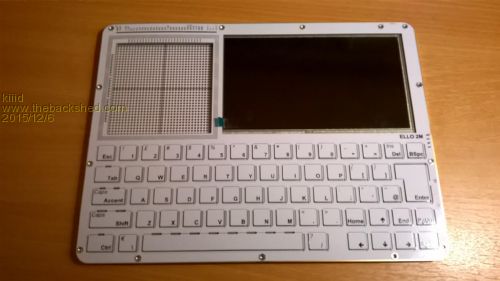
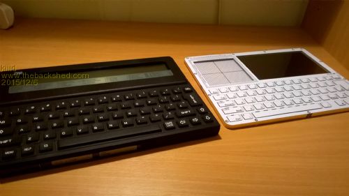
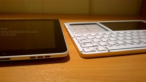
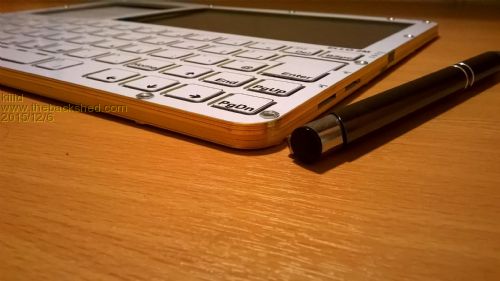
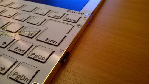
There are a few things about this computer, which I am really proud of. First, it is thin, I mean really thin - 6.4mm total. You can see it in the pictures (sorry about the quality) compared to the famous Z88, to an iPad, and to a typical pen. In size it is just about a standard A4 sheet. 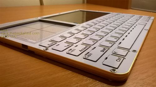
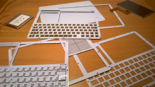
The second really cool thing is that it is ENTIRELY built from PCBs. No plastic enclosure, no moulds, no mechanical parts. The whole laptop is built as a stack of 6 PCBs with carefully designed shape and thickness. Add to those a 7" display panel and a battery, and that's everything it is. Eight components all in all, you can see them in one of the pictures. That makes it easy for assembling by pretty much anyone. I have even tried to work out a little bit of aesthetic design with the PCBs side plated with gold, round corners, etc... 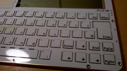
The keyboard design was fun. It is the top two panels, the first one being the keyboard layout with cutouts at suitable locations, so the buttons can be pushed. The PCB underneath is to provide a frame for the buttons and also to raise the panel so the buttons can be pushed. There is a separate microcontroller PIC16F1517 which takes care of scanning the keyboard and communicating with the MM+ via the console port, also controlling the power supply to everything and controlling an RGB status LED as well. It is the only part in the schematic which is on at all times. The keyboard optionally can be backlit as well. In order to reach this thin size I had to dump the use of pre-assembled display modules, and built the SSD1963-based display and XPT2046 touch controller on the main board. The laptop also has three micro-SD cards, one is permanently built-in emulating a 'hard drive', the other two and removable. You can see them on the right side of the keyboard. There is also an 'expansion port', which is a single row standard square pin receptacle. The whole laptop is powered and charged via micro-USB connector, which can be used also as console for the MM+ for the initial configuration. 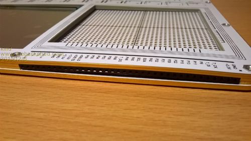
Additionally there is a really cool RF module built-in, which essentially emulates a wireless UART connection and also has an internal stack with ability for simple networking with similar devices. The range (by specs) is about 100 metres. Of course there is a real-time clock with a built-in coin battery as well. And a small buzzer. Of course being a first revision prototype didn't save me from some mistakes. In the original design I was planning to have a pre-routed (not a simple sea of holes) solderless prototyping space on the left side, which is built from four PGA-289 sockets. Unfortunately my mechanical calculations turned out a bit wrong and I will need to revise some details there. But in the release there will be a prototyping space as well. All this may sound really complex, but in fact the whole laptop is only eight chips and some small number of discrete components, connectors and other stuff. You can see it in the picture. 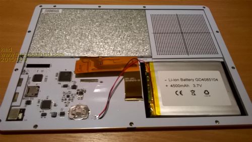
I still don't have these ready for distribution and I need to overcome some chronic shortage of funds, but if anyone is interested in details, pleas ask. Also, if anyone wants to help me out or cooperate in some way to get these sooner to a greater circle of people, please be very welcome. 
Konstantin http://rittle.org -------------- |
||||
| viscomjim Guru Joined: 08/01/2014 Location: United StatesPosts: 925 |
Hi Konstantin, the only thing that comes to mind right now is... H O L Y C O W !!!!!! This is a really cool effort. Can not wait to see this thing running. Very nice design using PCBs as the enclosure and the circuit. Very impressive. I wonder if this would be a good kickstarter or indigogo type thing. I know this is not production ready, but what is the cost to make one of these and what is your target cost? |
||||
| WhiteWizzard Guru Joined: 05/04/2013 Location: United KingdomPosts: 2978 |
Hi Kon, Great stuff you've created there with some 'unique' touches. Like Jim has asked, what is the approximate cost to manufacture one of these bearing in mind you mention six PCBs at A4 (ish) size. Also, what battery life are you seeing 'on average'? I see it is a 4500mAh battery so am guessing around 4-5 hours (with a decent backlight level). And whilst on the battery, what rate are you able to re-charge it at? Let's meet up soon (I will reply to your email later!!) so that I can see one in the flesh! I may be able to help you with some of the things you mention  . . . . . . . . . . . .
WW |
||||
| MicroBlocks Guru Joined: 12/05/2012 Location: ThailandPosts: 2209 |
Bravo!! Something i was toying with in my mind too for a long time, but i never figured out an easy way to manufacture it. This execution of an idea is just brilliant. i did made something with two stacked pcb's for a client before. Costs where saved by using some laser cut acrylic for the other layers. Maybe you could benefit from that too. We tried layers from thin wood also which i thought looked superb, but the client went with black acrylic. I really like the use of stacked PCB's though. It gives it a very distinct and unique look. Once you have some samples ready, i can show it to some people who are technology/programming teachers in Bangkok. I also have a good relation with one of the article writers for a major electronics magazine here in Thailand. If you can write an article and provide pictures/video and maybe some sample code they might be interested in publishing. Microblocks. Build with logic. |
||||
Lou Senior Member Joined: 01/02/2014 Location: United StatesPosts: 229 |
WoW !! Quite an amazing project there kiiid. That would be a great teaching aid for some Ham Radio clubs around here. Looks like you have put a ton of work on this, I will follow this project and show it to some of the local Ham clubs. Look at what you've done Geoff, opened up an entire planet of volunteer enthusiasts working together to create some of the neatest stuff in the world. BRAVO !! Now back to work on my uMite projects. Thanks to all on this forum, keep up the great work. Lou Microcontrollers - the other white meat |
||||
jman Guru Joined: 12/06/2011 Location: New ZealandPosts: 711 |
Konstantin Well done that's a fantastic result Regards Jman |
||||
| Geoffg Guru Joined: 06/06/2011 Location: AustraliaPosts: 3362 |
Simply amazing Kon. Such an original and unique design, not only a first in the Micromite world but unique in the world of electronics. Your PCBs were always marvels of precision but this has taken them to a whole new level. Congratulations. Geoff Graham - http://geoffg.net |
||||
| cwilt Senior Member Joined: 20/03/2012 Location: United StatesPosts: 147 |
Great job. Really creative use of materials. Love it. |
||||
| Frank N. Furter Guru Joined: 28/05/2012 Location: GermanyPosts: 1100 |
Hi Kon, I am very impressed! What should your laptop cost? It's really a large enrichment for the MM world!!! 
Frank |
||||
| atmega8 Guru Joined: 19/11/2013 Location: GermanyPosts: 738 |
Hollerdiewaldfee, if Steven Jobs could see this... Great Design, great Idea,great Project. Congratulations. |
||||
| kiiid Guru Joined: 11/05/2013 Location: United KingdomPosts: 671 |
Thanks all for the great feedback!
I will carry on with this and hope it will be available in the early 2016. As to the cost, so far I have made only 5 sets of boards, so it is a bit difficult to estimate what will be if this is made in some quantity. Generally speaking PCBs are cheap, and when manufactured as a lot - very cheap. For the first five prototype sets, the PCBs for one device come at about US$40, but I think that can be at least 4-5 times lower in quantity. I am still yet to fully complete the software for the keyboard controller and the laptop will be operational. Of course at the moment there is no support yet for the multiple drives or the RFD21733 module, but I hope these will come with time. Once I complete all my initial work on the prototypes and sort out any possible bugs, I am going to make the schematic available as well, so people can work their software if they are using the laptop. To @WW - I still don't have a clear picture about the battery life. My estimate is about 6-8 hours but the real picture will become known soon. Since I have made the device able to charge from a standard USB port, the charging current is about 450mA and it will take approximately 10 hours for a full charge. To @MB - it would be great if you can engage that magazine to publish something. Unfortunately I am just a hardware guy and probably unable to write articles or such things, but I am able to supply photos (or maybe a set of boards soon) so that can be done. If anyone has suggestions about this project, please let me know. I expect if everything goes well, I will be able to run some small demo programs on the 2M before the Christmas holidays and will post the results here. http://rittle.org -------------- |
||||
| kiiid Guru Joined: 11/05/2013 Location: United KingdomPosts: 671 |
Maybe also we will see in 2016 a MM+ based smartphone using the same PCB stack concept?
http://rittle.org -------------- |
||||
| Henk Newbie Joined: 06/10/2015 Location: NetherlandsPosts: 20 |
WOW! I only see this now.What a great work you did. Such I nice design. I am surprised at the low price for the PCB's for such not standard designs. Which company did produce these? I noticed this sentence in an earlier post from you "Also, if anyone wants to help me out or cooperate in some way to get these sooner to a greater circle of people, please be very welcome." I am willing to invest in a larger production of these PCB's if you want to get them to a wider circle of people. Just let me know. I wil spread them just for the production cost plus posting nothing more just for the hobby and the great fun you can have with this design. Great work! |
||||
| kiiid Guru Joined: 11/05/2013 Location: United KingdomPosts: 671 |
Thank you! It is great to see people are interested. The company that produced these first prototypes is NOA Labs in China. I have been working with them for years and their quality has always been great at very reasonable prices. If you are interested in letting this laptop make it to more people, please drop me a line at ybc-mail-com and we can have a chat in more details. Thanks, Konstantin http://rittle.org -------------- |
||||
| Henk Newbie Joined: 06/10/2015 Location: NetherlandsPosts: 20 |
I just did send you a PM. Henk |
||||
| kiiid Guru Joined: 11/05/2013 Location: United KingdomPosts: 671 |
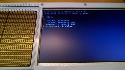
First, Merry Christmas to all! I have been working on the verification of the hardware and stumbled upon a problem with the SSD1963 chip. As someone might have noticed from the pictures that I posted earlier, I have the entire SSD1963 sub-circuit integrated on board. My problem is that I can't get it to work yet. On the hardware side all pins seem to be correct; I have verified all of them at least a few times and compared to other SSD1963-based circuits that I was able to dig up from the net. All supply voltages are correct, and MM+ doesn't say anything about problems during initialisation. I have tested the backlight current generator independently, and it works fine. After OPTION LCDPANEL SSD1963_7, L (tried with _7A as well) nothing happens and no error is returned from the MMbasic as well. Also the backlight is not getting any enabling signal which is supposed to be coming from SSD1963's PWM output. There is only one part in the whole assembly that I am unsure about - the crystal for SSD1963. Unfortunately I haven't been able to check what frequency is there in those Chinese modules that the MM+ has been tested with as I don't have one. Can someone please inspect one of these boards and let me know? I tried with 8MHz and 10MHz crystals on my board, but no luck. I see there is a healthy oscillation signal there, though. Also, is there any way that would allow me to check if MM+ actually talks successfully to SSD1963 and what information it gets from it, if any? Unfortunately I don't have much of equipment at home right now, only a small scope and a multimeter, so I can't hook up a logic analyser or other fancy stuff to verify more about the communication. Any additional info or suggestions are very welcome. Thanks! http://rittle.org -------------- |
||||
| kiiid Guru Joined: 11/05/2013 Location: United KingdomPosts: 671 |
Christmas miracles still happen apparently 
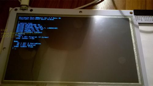
Finally got it to work. That allowed me to verify the touchscreen as well (and it is working fine). Will need to do a few little mods in the schematic and R2 final boards will be ready for everyone sometime in late January, I hope. http://rittle.org -------------- |
||||
| viscomjim Guru Joined: 08/01/2014 Location: United StatesPosts: 925 |
Hi Kiiid, out of curiosity, how did you get it to work, what was the problem? |
||||
| kiiid Guru Joined: 11/05/2013 Location: United KingdomPosts: 671 |
It was a small mistake in my schematic. The MM+ pins for reset and D/C of SSD1963 were swapped. Took me ages to discover it, because RS in the MM+ documentation actually refers to the D/C pins and at some stage during my design some time ago I have overlooked that fact. But it is fixed now. I wouldn't have been able to fix it so easily (not possible on the PCB as the traces are running on internal layers) without Geoff's help by sending me the MM+ sources which I modified slightly to get this revision only to work. Thanks for that. http://rittle.org -------------- |
||||
| kiiid Guru Joined: 11/05/2013 Location: United KingdomPosts: 671 |
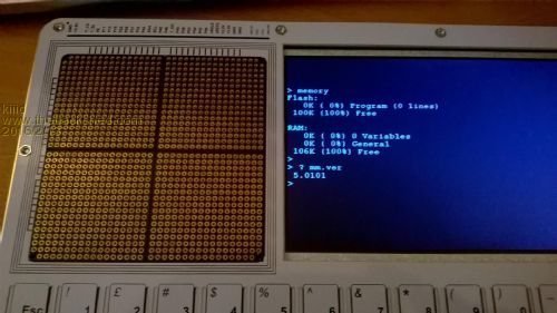
UPDATE: It is done! My MM-based laptop is alive and full. Took me a while to complete the keyboard/power controller (based on PIC16F1517), and make a few updates in the aesthetics of the keyboard panel for the future final revision. Had to fix two final hardware bugs existing in this revision, as well. The electronics prototyping space also does a good job. It is routed three 'bus' lines, 26 columns, each one made out of three sub-columns. The routing diagram is on the panel actually. There are still some drivers to be made for the MM+ to support the hardware features, but that is entirely software job from now on. I am planning to make a few of these initially. If someone wants a piece, please email me at knivd@me.com. The very first samples will be expensive unfortunately (around Ł60 for the entire kit), but anyone who has made boards knows why. I am also looking for some little funding help from people because the work so far has drained my budget. Currently I have the kit ready to go to the factory, but unfortunately not enough money to order it. If someone is interested in giving me a hand with that, please email me so we can discuss. The word is about a Ł1k or so, to make these a reality. If someone is interested in the schematics or other details, also please drop me a line. Thanks, Konstantin 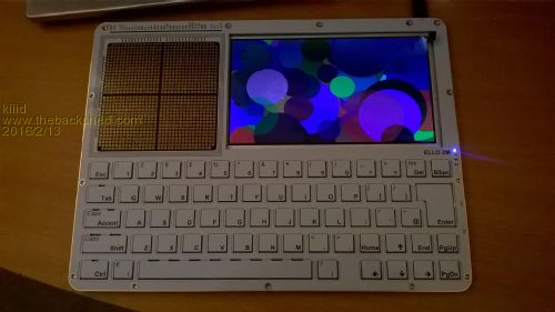
http://rittle.org -------------- |
||||
| Page 1 of 6 |
|||||
| The Back Shed's forum code is written, and hosted, in Australia. | © JAQ Software 2026 |
