
|
|
Forum Index : Microcontroller and PC projects : MMflash - Flashing MM’s made easy
| Page 1 of 3 |
|||||
| Author | Message | ||||
TassyJim Guru Joined: 07/08/2011 Location: AustraliaPosts: 6543 |
MMflash A wrapper for pic32prog.exe Pic32prog is a flash programming utility for Microchip PIC32 microcontrollers by Serge Vakulenko The ASCII mode was added by Robert Rozee. https://github.com/sergev/pic32prog The ASCII mode made it possible to use a low cost Arduino or Micromite to program PIC32 chip without the need for MPLAB and a Pickit3. Peter Mather wrote the CFUNCTION to allow the micromites to be used and Geoff Graham gave us MMBasic. This wrapper is the easy part. Unzip the files into any writable folder. MMflash write to the folder so it must have write permissions. "Program Files" is not a good location. Configure. 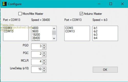
For Micromites, select the com port and baud rate that it is currently set at. The baud rate gets changed to 115200 during programming. You also need to set the pins that are used for the 3 functions PGD, PGC and MCLR. The line delay is needed during uploading the program. 10 (100ms) is the minimum that works reliably. For Arduino, usually the only setting is com port. -b3 is the most common setting for baud rates but you may have to try other settings. The settings are saved between sessions. Programming the Master PIC 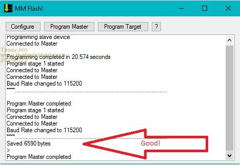
For the micromites, a successful load is indicated by the 'SAVED xxxx bytes' If you don't see this, it is worth trying again. For Arduinos the programming is much faster. Flashing the target PIC 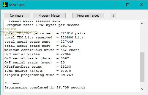
Select the HEX file and sit back. Windows only. Once the configuration is set, you can create a desktop shortcut and drag a HEX file onto the shortcut. MMflash will open and, after confirmation, start the flash process. Windows: MMflash.zip Linux 32bit: MMflash32.tar.gz Linux 64bit: MMflash64.tar.gz Help file: MMflash.pdf Jim VK7JH MMedit |
||||
CircuitGizmos Guru Joined: 08/09/2011 Location: United StatesPosts: 1427 |
This is fantastic! Well done! Micromites and Maximites! - Beginning Maximite |
||||
| matherp Guru Joined: 11/12/2012 Location: United KingdomPosts: 11603 |
Jim is underplaying what he has done . Pic32prog has been around for some time and with Rob's enhancement has made it possible to program PIC32 chips with very cheap hardware. However, it has always suffered from being a DOS application. You needed to open a DOS box, navigate within DOS to the program, remember a slightly obscure command line including constructing the DOS path to the relevant hex file - all perfectly functional but somewhat clunky. Jim has done all this for us with a simple windows GUI. I wrote a CFunction to allow one Micromite to program the firmware into another PIC32, but it suffered from all the issues of the DOS application + the need to program the host Micromite with the CFunction including modifying the program to select the pins you are using for connection, set the console baudrate to 115200, run the program, then run pic32prog, then set the baudrate back - even more clunky. With Jim's wrapper this now is so easy I've completely given up using the PicKit3 and used his tool to program 5.1 into all my development boards 
One warning: the Micromite CFunction will only run on a Micromite (MX170) that is loaded with V5.1 or a MM+ (MX470) that is running 4.7b37 or 5.1. So you need one up-to-date chip before you can then program any other chip (MX170s can be used to program MX470s). The program can of course also be used to load any other Hex file into any other PIC32. So for example it can be used to program the speech output code into a MX150. Programming speed is almost completely dependent on the PC serial connection to the host Micromite. In experiments I've found fastest is a "real" serial port (1'47"), next is a CH340 USB/UART (2'12") and Microblocks PIC16F1455 code (2' 21") , slowest is a "genuine" FTDI232 (3'47"). In all cases the console on the Micromite is set to 115200 baud. For anyone interested here is the source of the CFunction: /*******************************************************************************
* * Pic32prog CFunction for Micromite * * Entry point is function long long main(long *PGD, * long *PGC, * long *MCLR) * * ******************************************************************************/ #define Version 100 //Version 1.00 #include "../cfunctions.h" #define Dpinnum 0 #define Dreadport 1 #define Dsetport 2 #define Dclrport 3 #define DsetTRIS 4 #define DclrTRIS 5 #define Csetport 6 #define Cclrport 7 #define Dpin 8 #define Cpin 9 #define GD 10 #define GC 11 #define DEVID (*(volatile unsigned int *)0xBF80F220) #define RBUF_SIZE 1024 #define newchar do{IN = getConsole();if(IN!=-1)ringBufS_put(rb,(unsigned char)IN);} while (IN!=-1); #define pulsePGC *(volatile unsigned int *)pins[Csetport]=pins[Cpin] ; k=DEVID; *(volatile unsigned int *)pins[Cclrport]=pins[Cpin]; k=DEVID; typedef struct ringBufS { unsigned char buf[RBUF_SIZE]; int head; int tail; int count; } ringBufS; unsigned int modulo_inc (const unsigned int value, const unsigned int modulus) { unsigned int my_value = value + 1; if (my_value >= modulus) { my_value = 0; } return (my_value); } unsigned int modulo_dec (const unsigned int value, const unsigned int modulus) { unsigned int my_value = (0==value) ? (modulus - 1) : (value - 1); return (my_value); } int ringBufS_get (ringBufS *_this) { int c; if (_this->count>0) { c = _this->buf[_this->tail]; _this->tail = modulo_inc (_this->tail, RBUF_SIZE); --_this->count; } else { c = -1; } return (c); } void ringBufS_put (ringBufS *_this, const unsigned char c) { if (_this->count < RBUF_SIZE) { _this->buf[_this->head] = c; _this->head = modulo_inc (_this->head, RBUF_SIZE); ++_this->count; } } int ringBufS_empty (ringBufS *_this) { return (0==_this->count); } void ringBufS_flush (ringBufS *_this) { int j; _this->count = 0; _this->head = 0; _this->tail = 0; for(j=0;j<RBUF_SIZE;j++)_this->buf[j]=0; } int clock1(int pins[], int D) { int j=pins[Dpin],k; *(volatile unsigned int *)pins[DclrTRIS]=j; if(D) { *(volatile unsigned int *)pins[Dsetport]=j ; } else { *(volatile unsigned int *)pins[Dclrport]=j; // PGD = hi-Z } pulsePGC return D; } int clock4(int pins[], int TDI, int TMS) { int i=0,j=pins[Dpin],k; *(volatile unsigned int *)pins[DclrTRIS]=j; if(TDI) { *(volatile unsigned int *)pins[Dsetport]=j ; } else { *(volatile unsigned int *)pins[Dclrport]=j; } pulsePGC if(TMS) { *(volatile unsigned int *)pins[Dsetport]=j; } else { *(volatile unsigned int *)pins[Dclrport]=j; } pulsePGC *(volatile unsigned int *)pins[DsetTRIS]=j; pulsePGC k=DEVID; //waste a couple of cycles k=DEVID; i=(*(volatile unsigned int *)pins[Dreadport] & j)>>pins[Dpinnum]; pulsePGC return i; } long long main(long *PGDv, long *PGCv, long *MCLRv){ static const unsigned char announce[] = "ascii ICSP V1M" ; int PGD=*PGDv,PGC=*PGCv,MCLR=*MCLRv; int IN,pins[12],i,UP,CHAR; char ch,active=1,J,B,I,PrAcc,*p; ringBufS *rb; p=GetTempMemory(RBUF_SIZE+256); rb=(void*)p; ringBufS_flush(rb); pins[Dsetport]=(int)(volatile unsigned int *)GetPortAddr(PGD,LATSET); pins[Dclrport]=(int)(volatile unsigned int *)GetPortAddr(PGD,LATCLR); pins[DsetTRIS]=(int)(volatile unsigned int *)GetPortAddr(PGD,TRISSET); pins[DclrTRIS]=(int)(volatile unsigned int *)GetPortAddr(PGD,TRISCLR); pins[Dreadport]=(int)(volatile unsigned int *)GetPortAddr(PGD,PORT); pins[Dpinnum]=GetPinBit(PGD); pins[Dpin]=1<<pins[Dpinnum]; pins[GD]=PGD; pins[GC]=PGC; pins[Csetport]=(int)(volatile unsigned int *)GetPortAddr(PGC,LATSET); pins[Cclrport]=(int)(volatile unsigned int *)GetPortAddr(PGC,LATCLR); pins[Cpin]=1<<GetPinBit(PGC); while(active){ newchar if(!ringBufS_empty(rb)){ I=(char)ringBufS_get(rb); CHAR=0; if(I>='a' && i<='z'){ UP=0; I-=32; //convert to upper case CHAR=1; } else if(I>='A' && i<='Z') { UP=1; CHAR=1; } if(CHAR){ if ((I >= 'I') && (I <= 'X')){ J= I-'I'; B = 0; if (clock4(pins, J & 1, 0)) B |= 1; if (clock4(pins, J & 2, 0)) B |= 2; if (clock4(pins, J & 4, 0)) B |= 4; if (clock4(pins, J & 8, 0)) B |= 8; ch = 'I' + B; if (UP) { putConsole(ch); } } else { if(I=='D'){ // TDI = 0, TMS = 0, read_flag = 0 ch = '0' + clock4(pins, 0, 0); if(UP)putConsole(ch); } else if(I=='E'){ // TDI = 0, TMS = 1, read_flag = 0 ch = '0' + clock4(pins, 0, 1); if(UP)putConsole(ch); } else if(I=='F'){ // TDI = 1, TMS = 0, read_flag = 0 ch = '0' + clock4(pins, 1, 0); if(UP)putConsole(ch); } else if(I=='G'){ // TDI = 1, TMS = 1, read_flag = 0 ch = '0' + clock4(pins, 1, 1); if(UP)putConsole(ch); } else if(I=='A') { // TDI = 0, TMS = 1-0-0, read_flag = 0 clock4(pins, 0, 1); // (data header) clock4(pins, 0, 0); ch = '0' + clock4(pins, 0, 0); if(UP)putConsole(ch); } else if(I=='Z') { // TDI = 0, TMS = 1-0, read_flag = 0 clock4(pins, 0, 1); // (data footer) clock4(pins, 0, 0); } } } else { if(I=='0') { // clock out a 0 bit on PGD pin clock1(pins, 0); // PGD = 0 } else if(I=='1') { // clock out a 1 bit on PGD pin clock1(pins, 1); // PGD = 1 } else if(I=='-') { // clock in single PGD bit ch = '0' + clock1(pins, 1); putConsole(ch); } else if(I=='+') { // TDI = 0, TMS = 0, accumulate PrAcc if (!clock4(pins, 0, 0)) PrAcc = 0; // remember if any error ('0') } else // '>', '.', '=': handshake and formatting commands, placed here for possible speed if(I=='>') { // request a sync response of '<' putConsole('<'); } else if(I=='=') { // retrieve value of PrAcc putConsole(PrAcc ? '1' : '0'); PrAcc = 1; // reset to default } else // the remaining commands have no great speed requirements, therefore can use // the slower Micromite library routines // '2','3': pulse MCLR high, clock out signature, set MCLR high if(I=='2') { // set MCLR low PinSetBit(MCLR, LATCLR); // MCLR = 0 } else if(I=='3') { // set MCLR high PinSetBit(MCLR, LATSET); // MCLR = 1 } else // '4','5': control power supply to target if(I=='4'){ // turn power to target OFF ExtCfg(PGD,EXT_NOT_CONFIG,0); ExtCfg(PGC,EXT_NOT_CONFIG,0); ExtCfg(MCLR,EXT_NOT_CONFIG,0); active=0; } else if(I=='5'){ // turn power to target ON ExtCfg(MCLR,EXT_DIG_OUT,0); PinSetBit(MCLR, LATCLR); ExtCfg(PGD,EXT_DIG_OUT,0); PinSetBit(PGD, LATCLR); ExtCfg(PGC,EXT_DIG_OUT,0); PinSetBit(PGC, LATCLR); } else // miscellaneous other commands if(I=='8') { // insert 10mS delay for(i=0;i<20;i++) uSec(500); newchar } else if(I=='?') { // return ID string, "ascii ICSP v1X" MMPrintString(announce); /* putConsole('a'); putConsole('s'); putConsole('c'); putConsole('i'); putConsole('i'); putConsole(' '); putConsole('I'); putConsole('C'); putConsole('S'); putConsole('P'); putConsole(' '); putConsole('v'); putConsole('1'); putConsole('M'); //Micromite!!!*/ } } } } // end of while do { IN = getConsole(); //strip any junk characters } while (IN!=-1); return pins[Csetport]; } |
||||
Grogster Admin Group Joined: 31/12/2012 Location: New ZealandPosts: 9984 |
@ Jim - sorry about this, but: 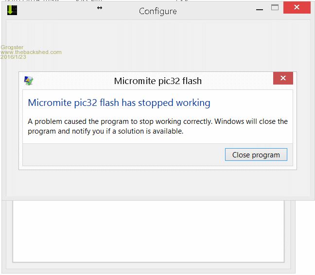
- Fire up MMflash - Click on CONFIGURE button - Click on Arduino Master to put the tick in that check-box - Click OK - Click CONFIGURE button again - Crashes here. Smoke makes things work. When the smoke gets out, it stops! |
||||
| TassyJim Guru Joined: 07/08/2011 Location: AustraliaPosts: 6543 |
Didn't you read the subject title "Flashing made easy" I have tried to reproduce the error on a couple of different PC's without any joy. I assume you are running W8 or W8.1 - I don't have either of those anymore. Where did you install the files to ? You shouldn't have a MMflash.inf file yet. If you do, can I see the contents. If you don't Start MMflash and then close it. That should create the MMflash.inf file. Did you have the Arduino plugged in during configure? MMflash looks for any existing and available ports. If there aren't any, a message should pop up. This takes a few seconds but closing 'configure' befre it has finished searching doesn't seem to matter. Jim I had better ask, what antivirus do you run? VK7JH MMedit |
||||
centrex Guru Joined: 13/11/2011 Location: AustraliaPosts: 320 |
Hi Tassy Great work but I have a problem? The configure works Program master seems to work Program target does not this is what I get after doing all the above... 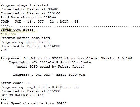
it has an error -1 and only takes about 0.5 secs Any advice 32bit win7 Cliff Cliff |
||||
| TassyJim Guru Joined: 07/08/2011 Location: AustraliaPosts: 6543 |
The line with "Adapter: . OK1 OK2 - ascii ICSP v1M" tells us that we are talking to the CFUNCTION OK. I suspect that the connection between the Master and Target is not correct. PIN numbers wrong, no ground or no power. Just tested with the Target not connected and I received the same messages here. Jim VK7JH MMedit |
||||
| Bizzie Senior Member Joined: 06/07/2014 Location: AustraliaPosts: 192 |
I too am having problems! BUT I am not getting as far. I have never seen the saved XXXX message. here is what I get. Program stage 1 started
Connected to Master at 38400 Connected to Master at 115200 Baud Rate changed to 115200 COM4 PGD = 25 : PGC = 24 : MCLR = 26 ****.................................................................................................... Program Master completed I believe I have 5.1 loaded on a 170 see below :- Micromite MKII MMBasic Ver 5.1
Copyright 2011-2016 Geoff Graham > memory Flash: 1K ( 1%) Program (11 lines) 59K (99%) Free RAM: 0K ( 0%) 0 Variables 0K ( 0%) General 53K (100%) Free > list Dim Cnt As integer = 0 Trace on Do Cnt = Cnt + 1 Print "Hello ";Cnt Pause 200 If cnt > 5 Then Trace off Loop > The MM is on one of BigMick's backpack boards with no display connected. Rob White |
||||
| TassyJim Guru Joined: 07/08/2011 Location: AustraliaPosts: 6543 |
It looks like we didn't get a command prompt when first connecting. I have done an update to the program to give some more feedback (and a couple of cosmetic changes). A correct Program Master should now look like: Program stage 1 started
Connected to Master at 38400 > OPTION BAUDRATE 115200 Connected to Master at 115200 Baud Rate changed to 115200 COM13 PGD = 3 : PGC = 2 : MCLR = 4 ****................................................... Saved 6606 bytes > Program Master completed I have added a crtl-C and more delays. The first ">" is new and if not present, we are not talking to the 'mite. You can download the full ZIP again or just change the EXE with the one in this attached. 2016-01-24_052247_MMflash_exe.zip Based on this feedback, I will add a few more informative messages. Jim VK7JH MMedit |
||||
| centrex Guru Joined: 13/11/2011 Location: AustraliaPosts: 320 |
Tassy Just tried it all again SUCCESS this time 110 secs. Dont know what I did the first time but it all works Many thanks Cliff Cliff |
||||
| Grogster Admin Group Joined: 31/12/2012 Location: New ZealandPosts: 9984 |
Yeah, so? 
Installed to C:\MMflash I do. Here it is(in a code box): [Windows] ; Main Window MainX = 200 MainY = 200 MainW = 468 MainH = 287 ; Config Window ConfigX = 200 ConfigY = 200 ConfigW = 500 ConfigH = 290 [micromite] uM comport = com7 uM SerialSpeed = 38400 LineDelay = 150 PGD = 3 PGC = 2 MCLR = 4 [Arduino] A comport = com7 A SerialSpeed = -b3 [General] Master Device = micromite MM Program = pic32prog.bas HEX File = *.hex HEX Folder = No. I will try that first, and let you know. AVG Free 2016, up to date. Smoke makes things work. When the smoke gets out, it stops! |
||||
| Grogster Admin Group Joined: 31/12/2012 Location: New ZealandPosts: 9984 |
UPDATE: Makes no difference if I have the Arduino plugged in or not, although MMflash DOES correctly see it there as COM5. Here is a short video showing start to finish and the crash. There is no sound on this video, it is silent. Smoke makes things work. When the smoke gets out, it stops! |
||||
| Bizzie Senior Member Joined: 06/07/2014 Location: AustraliaPosts: 192 |
Jim, I do not see the prompt. Here is the output from two tries:- Program stage 1 started Connected to Master at 115200 COM4 PGD = 25 : PGC = 24 : MCLR = 26 ****................................................... Program Master completed Program stage 1 started Connected to Master at 115200 COM4 PGD = 25 : PGC = 24 : MCLR = 26 ****................................................... Program Master completed The Rx/Tx leds flash on the USB-Serial adapter (freetronics) and I can talk with the MM using TT. Rob White |
||||
| TassyJim Guru Joined: 07/08/2011 Location: AustraliaPosts: 6543 |
Rob, This time we tried to connect to the Master at 115200 baud. Is that correct or should it still be 38400? Testing with Teraterm will confirm the correct rate. It looks like MMFlash now thinks it is 115200 but the mite is actually at 38400 or some other speed. I will add a few more checks and debug reports to help. Grogster, Thanks for the video, I was hoping for dancing girls... Can you try this replacement exe. It is MMflashA.exe and put it in the same folder as the others. I have made some changes to the compiler options. 2016-01-24_064519_MMflashA.zip Jim VK7JH MMedit |
||||
| Bizzie Senior Member Joined: 06/07/2014 Location: AustraliaPosts: 192 |
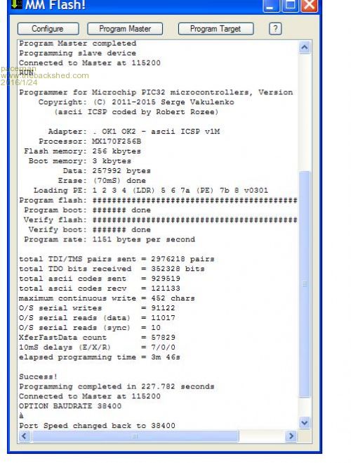
Jim, An update. I started a fresh setting baudrate to 38400 and all worked this time. I was sure I did that before but may not of as I usually run at 115200. Now there is an error code: 1 See below Program Master completed Program stage 1 started Connected to Master at 38400 > OPTION BAUDRATE 115200 Connected to Master at 115200 Baud Rate changed to 115200 COM4 PGD = 25 : PGC = 24 : MCLR = 26 ****................................................... Saved 6609 bytes > Program Master completed Programming slave device Connected to Master at 115200 RUN Programmer for Microchip PIC32 microcontrollers, Version 2.0.186 Copyright: (C) 2011-2015 Serge Vakulenko (ascii ICSP coded by Robert Rozee) Adapter: . OK1 OK2 - ascii ICSP v1M Processor: MX170F256B Flash memory: 256 kbytes Boot memory: 3 kbytes Data: 491700 bytes total TDI/TMS pairs sent = 151 pairs total TDO bits received = 72 bits total ascii codes sent = 73 total ascii codes recv = 27 maximum continuous write = 24 chars O/S serial writes = 9 O/S serial reads (data) = 3 O/S serial reads (sync) = 0 XferFastData count = 0 10mS delays (E/X/R) = 0/0/0 elapsed programming time = 0m 00s Error code: 1 Programming completed in 0.917 seconds Connected to Master at 115200 OPTION BAUDRATE 38400 ��� Port Speed changed back to 38400 Rob White |
||||
| TassyJim Guru Joined: 07/08/2011 Location: AustraliaPosts: 6543 |
Make sure the pins you are using are not wired to anything else. On the BackPack170 boards I have, PIN26 is used for the backlight and has components connected even with the display unplugged. Jim VK7JH MMedit |
||||
| robert.rozee Guru Joined: 31/12/2012 Location: New ZealandPosts: 2541 |
this tells me that you are likely failing at the first command sent to the PIC32 that is of any substantial length. the question arises: at 115,200 baud can the micromite accept a sustained string of characters without falling out of sync? to work with pic32prog the micromite needs to be able to accept up to 500 characters in a burst, at 115,200 baud, 8 data bits, no parity, 1 stop bit. all the while operating without a crystal (unless a MM+). you may find it necessary to tweak the RC clock frequency using: OPTION CLOCKTRIM �n try trim values of +1 or -1 at first, and see if the value of 'total TDI/TMS pairs sent' goes up. alternatively, have the micromite loop measuring a known frequency generated from your PC sound card to arrived at the necessary trim setting. cheers, rob :-) |
||||
| matherp Guru Joined: 11/12/2012 Location: United KingdomPosts: 11603 |
The Micromite on which I developed the CFunction needs clocktrim -9 to be exactly correct and despite this the program works fine at default. The CFunction includes a 1024 circular buffer which coupled with the 128 byte buffer in the Micromite firmware (hardware receive interrupt driven) ensures that characters should never be lost. As Jim says, most likely cause is a problem with a conflict on the ISCP connection pins either on the host or the target. |
||||
| paceman Guru Joined: 07/10/2011 Location: AustraliaPosts: 1329 |
Hi Jim - another great utility for the Micromite. Thanks for your efforts, and of course Jim, Peter and Serge as well - we're all going to enjoy this. ----------- I downloaded your original MMFlash onto my old WinXP system last night and have just successfully flashed one of Mik's SMD MX170 Backpacks via another MX170 with MM2 V5.1 loaded. The steps were: 1. Flashed a new MX170 with the MM2 V5.1 software using my Pickit3. 2. Ran MMFlash from the folder that it unzipped into, without anything connected. Then closed it so that it set up the config.inf file into that folder. 3. Wired everything up: i.e. the XP notepad via a USB/serial converter and the console to the MM2 V5.1 Master - and the Master to the Target MX170 (one of Mik's SMD Backpacks). I used the same pins you showed in the screenshot of your first post for MCLR, PGD & PGC to the Backpack ICSD pins. Power and ground of the ICSD connector were connected from the Master MX170's supply. 4. Ran MMFlash again, entered the correct COM port number and the baudrate to 38400. (I put it in the wrong MMFlash box to start with  ) )
5. Hit the "Program Master" button and got the output in first screen below. (I think I may have had to hit the "Configure" button again before I did this, but can't remember). 6. Hit the "Flash Target" button, navigated to where I had the MM2 V5.1 .hex file when it asked for it and away it went. 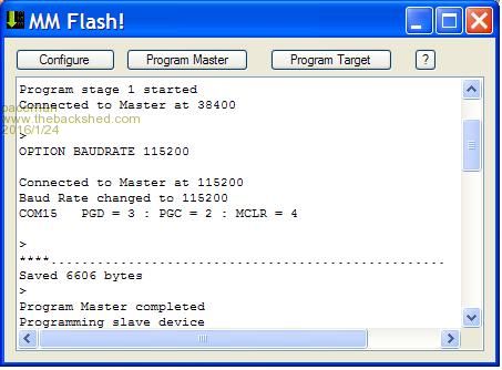
|
||||
| paceman Guru Joined: 07/10/2011 Location: AustraliaPosts: 1329 |
I missed Jim's post above about pin 26 on Mik's Backpack. I had already (some months ago) disconnected the diode's connection to pin 26 - so that might be Rob's issue. Greg |
||||
| Page 1 of 3 |
|||||
| The Back Shed's forum code is written, and hosted, in Australia. | © JAQ Software 2026 |
