
|
|
Forum Index : Microcontroller and PC projects : Triggerd PWM..
| Page 1 of 4 |
|||||
| Author | Message | ||||
| Zonker Guru Joined: 18/08/2012 Location: United StatesPosts: 772 |
Evening Gents.. I was wondering if there is a way to do turn-on phase control using the PWM command... I can't think of a way to program this... If the PWM command had a trigger input pin to start the PWM frame, then set the freq to ether 50 or 60 hertz, it should work... I was looking to try and control SCR's of triac's to make a basic lamp dimmer or DC power supply controller... And then maybe try it with 3 phase... Any feedback thoughts would be awesome..!  |
||||
| Geoffg Guru Joined: 06/06/2011 Location: AustraliaPosts: 3353 |
In response to a request by kiiid (see this thread) I added to V5.1 a small feature that might do what you want. Now, whenever you use the PWM command (or SERVO) the timer that generates the PWM output will be reset to zero. This means that the rising edge of the next PWM pulse will start immediately following the PWM command. You do not have to change the PWM frequency or ratio for this reset to happen. Just use the command with the previous arguments is enough to resync the PWM output. So, perhaps the PWM command itself may be the trigger that you are looking for. For example: ' trigger on the positive edge of the 60Hz mains cycle
SETPIN 4, INTH, TRIG DO ' main program loop LOOP SUB TRIG ' set the frequency slightly lower than 60Hz so that the ' PWM command will restart the cycle PWM 58, dutycycle, etc END SUB Disclaimer: I have not tested this and I am not even sure that it is what you want. Geoff Geoff Graham - http://geoffg.net |
||||
| Geoffg Guru Joined: 06/06/2011 Location: AustraliaPosts: 3353 |
Another idea occurred to me... you could use the pulse command which runs in the background when the pulse width is over 3ms. The falling edge of the pulse on pin 5 would be the trigger for the SCR: ' trigger on the positive edge of the 60Hz mains cycle
SETPIN 4, INTH, TRIG SETPIN 5, DOUT ' this is the pulse output pin DO ' main program loop LOOP SUB TRIG PULSE 5, pulsewidth END SUB Another approach would be to use a timer: ' trigger on the positive edge of the 60Hz mains cycle
SETPIN 4, INTH, TRIG SETPIN 5, DOUT ' this is the pulse output pin DO ' main program loop LOOP SUB TRIG SETTICK pulsewidth, TICK END SUB SUB TICK PULSE 5, 0.1 ' trigger for the SCR SETTICK 0 ' stop the timer from repeating END SUB This will give a 100uS pulse to trigger the SCR. These will need checking to make sure that the interrupt latency and timing jitter do not cause a problem with your circuit. Geoff Geoff Graham - http://geoffg.net |
||||
| Zonker Guru Joined: 18/08/2012 Location: United StatesPosts: 772 |
Thanks Geoff..! Maybe this can work after all..! Will get some parts and give it a try.. Should be interesting... The MM's are truly a very versatile IC..! |
||||
Chopperp Guru Joined: 03/01/2018 Location: AustraliaPosts: 1123 |
@Zonker Hi, Did you ever progress with this phase control idea? Thanks. ChopperP |
||||
| Zonker Guru Joined: 18/08/2012 Location: United StatesPosts: 772 |
Hey Chopper.. Actually, no, I never got the time to try it... But, at work, there is a "renewed" interest to replace a 3-phase gate control SCR based firing board that they are having trouble getting parts for... So, maybe I might get a chance to do some head scratching on the topic after all..  I work for a company (Bitrode Corp) that manufactures Battery production and chemistry life cycle testing equipment... About 60% of there business still uses SCR based programmable DC supply's to create the DC source needed... However, their 3-phase control uses 6 SCR's to form a controlled DC source that can produce DC voltages that can be either positive or negative... So the design is a bit more complex than most... The MPU must also check for phase rotation and phase loss and shutdown the SCR firing sequence properly... The "fount end" circuits must also track and correctly detect the zero cross for each phase from 12 to 600 volts with out any parts changes on the board... I work for a company (Bitrode Corp) that manufactures Battery production and chemistry life cycle testing equipment... About 60% of there business still uses SCR based programmable DC supply's to create the DC source needed... However, their 3-phase control uses 6 SCR's to form a controlled DC source that can produce DC voltages that can be either positive or negative... So the design is a bit more complex than most... The MPU must also check for phase rotation and phase loss and shutdown the SCR firing sequence properly... The "fount end" circuits must also track and correctly detect the zero cross for each phase from 12 to 600 volts with out any parts changes on the board... Anyway, I have an Idea about the front end circuits needed, but I thought the MPU would need at least 3 "timer capture" hardware circuits inside to get the job done... I am not sure that the MM can do all this stuff in software, but, I could be wrong... I have been working on rewiring my brother Dave's 2 place Firestar II airplane to get it ready for night flight operations, so that has been taking up most of my time left on weekends... As usual, time is the main problem for me... I will find the parts an get a schematic going and see what can be done..  Single phase control would be a bit easier to try first... |
||||
| Chopperp Guru Joined: 03/01/2018 Location: AustraliaPosts: 1123 |
Hi Zonker, Thanks for the reply. Sounds like an interesting job you have. Single phase would definitely be much simpler to start with. You've given me some more food for thought. I'm sort of looking at a 230V - ~70V battery charger at about 15 - 20A. I've a nice big toroidal transformer that I may be able to put into service for the task. I built phase controlled chargers a good while ago now using a 555 timer to vary the firing angle of an SCR. They worked OK, but I was thinking that a MM might be more versatile. However, there are certainly quite a few things to consider using a MPU of any sort for this sort of thing. May do some head scratching myself. There will be a fair few planes flying around my area tomorrow as we have a bit of an airshow going on at the City airport not far away. Good luck with your task with your brother's plane. Thanks again ChopperP |
||||
| Zonker Guru Joined: 18/08/2012 Location: United StatesPosts: 772 |
Zero cross detection... I was wanting to use this part along with an opto to create a safe detection circuit that has the advantage of a very wide input voltage range without any value changes in the PCB design... Yep... The start of the head scratching...  2018-05-21_132736_DS98729AIXCP-CY10M90S.zip As always, feedback welcome... |
||||
| CaptainBoing Guru Joined: 07/09/2016 Location: United KingdomPosts: 2171 |
Zero crossing detect is fairly easy. Your could use this with a variable pad layout for the resistor. I use this a lot but note the current limiting resistor. You could experiment wit what value works for you to get the size down a bit. http://www.fruitoftheshed.com/Circuit%20Ideas.Really-Simple-Zero-Crossing-Detect.ashx |
||||
| LouisG Senior Member Joined: 19/03/2016 Location: AustraliaPosts: 130 |
Hi Zonker, 3-phase can definitely be done. Here's a little 3-phase fan controller I built overseas back in 2003 using triacs. The customer refused to have single phase exhaust fans in his factory. I made up half a dozen of these for proof of concept. The circuit is bare bones and absolute minimalist based on a PIC12C508A, an 8-pin OTP microcontroller, which was the cheapest PIC available at the time. That's it hiding behind the knob. 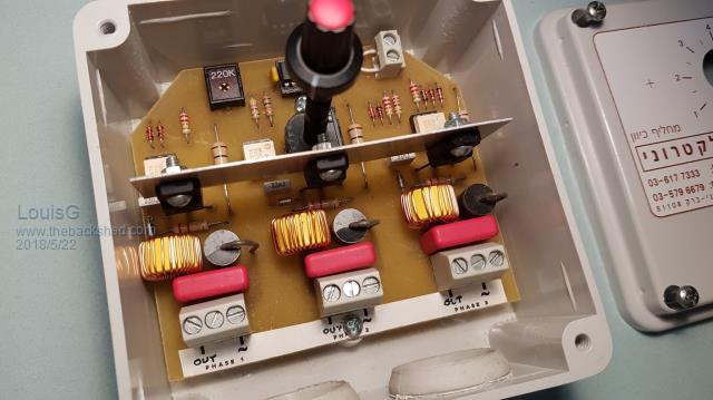 Some info: 400VAC 3-ph 50Hz 2A full-wave, half-controlled, no neutral connection. Operates with either forward or reverse phase sequence Loss of phase protection (which could cause motor burnout) Minimum speed trimmer Link for connecting a thermo-switch (motor protection) Triacs are 800V 12A isolated tab types White ICs are opto-triacs Software is in Assembler. Controllers were still operating when I enquired two years ago. Project discontinued when stricter EMC requirements came into force that year and anyway I was returning to Oz. I wish I had a Micromite back then. That PWM enhancement by Geoff makes it perfect for this application. - |
||||
| Chopperp Guru Joined: 03/01/2018 Location: AustraliaPosts: 1123 |
@LouisG Good looking Unit ChopperP |
||||
bigmik Guru Joined: 20/06/2011 Location: AustraliaPosts: 2979 |
Hi Louis, Are they MOC3021 devices hiding in plain sight there? Mick Mick's uMite Stuff can be found >>> HERE (Kindly hosted by Dontronics) <<< |
||||
| Chopperp Guru Joined: 03/01/2018 Location: AustraliaPosts: 1123 |
Probably the white thingies behind the heatsink. Then again, they could be something else ChopperP |
||||
| Warpspeed Guru Joined: 09/08/2007 Location: AustraliaPosts: 4406 |
I have seen a great many different approaches to this particular problem, some simple, some vastly more complex. The most clever simple solution used a voltage controlled oscillator as the main control element. Each phase has its own zero crossing detector that resets a counter at each zero crossing. The VCO then clocks the three counters, one per phase, with the same identical clocking frequency. Each counter will then produce an identical time delay between zeroing at the zero crossing, and final overflow. Phase rotation then becomes irrelevant as the phase delaying counter on each phase operates completely independently of the others. I cannot claim this as my own original idea, but its brilliantly simple, very effective, as it guarantees exactly identical phase delays on each phase. Cheers, ĀTony. |
||||
| Chopperp Guru Joined: 03/01/2018 Location: AustraliaPosts: 1123 |
Hi Warpspeed Can you recall the VCO freq & the resulting period resolution of the gating pulses after going through the counters? I.E. , how fine was the phase adjustment? Also, were the gating pulse a constant width? Thanks ChopperP |
||||
| Warpspeed Guru Joined: 09/08/2007 Location: AustraliaPosts: 4406 |
Its all so very long ago, I cannot now remember the exact details, it was just a piece of equipment I was once called upon to repair at the time, but was really impressed with the design philosophy and how well it worked, and it stuck in my memory. I suppose the longest delay required might be 10mS. If the counter was divide by 128, then the lowest VCO frequency might be 12.8Khz. If the highest VCO frequency was 256 Khz, that would give a time delay range range of 20:1. A faster VCO or lower division rate will get you a wider control range. But beware of time jitter, as the VCO is not locked to the mains, and there will be a one count ambiguity in the period measurement. The numbers can be juggled around a fair bit to get the desired results. From memory,the VCO was a simple 4046, and the counters one of the CMOS ripple counters possibly a 4020 or something similar. In most rectifier circuits there is usually no requirement to control the output right down to absolute zero, but to control and regulate over some reasonable range of mains input voltage and dc output current. Cheers, ĀTony. |
||||
| Chopperp Guru Joined: 03/01/2018 Location: AustraliaPosts: 1123 |
Hi Tony, Thanks for that info. Makes sense. I made some phase controlled single phase battery chargers many moons ago using a 555 time in mono mode, triggered at cross-over. Had a JFET wired as a source follower controlling the volts on the Control pin of the 555. This adjusted the pulse width & thus the firing angle of an SCR in series after a full wave bridge rectifier. The JFET itself was controlled by a couple of OPAMPS monitoring both the volts & current. The system was a bit rough around the edges but seemed to work OK. Still use one of them. (12V - 24V - 36V @ 20A) Regards Brian ChopperP |
||||
| Warpspeed Guru Joined: 09/08/2007 Location: AustraliaPosts: 4406 |
Three phase offers some interesting challenges, as very often the phase rotation can be wrong, and that can lead to disaster. Things like wind turbines not only have a wide input voltage range, but also a wide operating frequency. But phase control offers a very efficient and pretty robust means of control. Cheers, ĀTony. |
||||
| Chopperp Guru Joined: 03/01/2018 Location: AustraliaPosts: 1123 |
I haven't seen any disasters but have seen a ground surveillance Radar Antenna turning the wrong way after a UPS upgrade by contractors. 10 min fix. ChopperP |
||||
| Warpspeed Guru Joined: 09/08/2007 Location: AustraliaPosts: 4406 |
Three phase motors can be fun when they turn the wrong way. It can be pretty dangerous with large woodworking or workshop machinery. Cheers, ĀTony. |
||||
| Page 1 of 4 |
|||||
| The Back Shed's forum code is written, and hosted, in Australia. | © JAQ Software 2026 |
