
|
|
Forum Index : Microcontroller and PC projects : DXF CAD file conversion to RS-274X
| Page 1 of 2 |
|||||
| Author | Message | ||||
| Clockmanfr Guru Joined: 23/10/2015 Location: FrancePosts: 437 |
Hi Yahoo2 suggested I re-post in here. Hi. I have been doing the OzInverter New 6kW-15kW Power Board. For my use and individual masks for this large A4 size board, I have CAD software TCW Pro14, it does the boards and the separate layer masks, no probs. Now it seems that to get these Power Boards made, (seems other folk would like them ready made), at PCB manufactures ShenZhen2u or other PCB folk. They request RS-274X gerber files. Here below is what my CAD files can be exported as...... 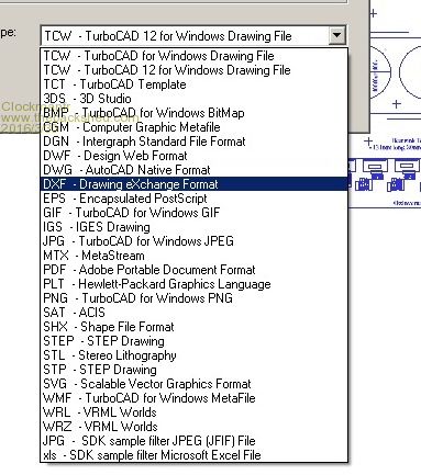
I see that there is reasonable cost software on the market that can do conversions, like GerberView etc, but I am not sure it this software will work.? My JPG files of the layers/masks comes out real nice, and at real size. PDF come out to scale but some pads have turned octagon, and no longer round. I really do not want to spend monies on PCB software and start again. Any help or advice would be appreciated. Thanks. -------------------------------------------------------------------------------- I have looked at Eagle, but the board I am doing is 282mm x 174mm double sided. So the Eagle low cost option is out. I looked at PADS, very costly. I looked at Autotrax but again no particular mention of importing DXF etc. Sprint layout 6, at least says it can import a file and use as background and you can build the PCB board over it. But 284 holes again! All the file conversion software mentions PDF, DXF to gerber, but only under circumstances when the PDF DXF is a created source file. So it seems that even Auto CAD to gerber needs modifying as the track size and other vectors disappear when gerber, so you need a gerber view to modify the gerber. So if I get this right.....? Ordinary DXF, PDF files can not be converted to gerber unless modified, and the PCB software folk have limited mentions of functions. The Ace Translator 3000 software seems, in there blurb, to offer a solution but the price for a single user is $700. for a couple of boards....Wow. To see the gerber you need a gerber viewer. To get the PCB to suit the manufacturers, I disregard CAD, and I need to start again and buy some PCB software, and learn. Once the PCB is created, the particular PCB software companies files need converting to RS-274X. Personally I have not done a PCB since the 1980's, and it seems that in the last 30 years or so, the PCB brigade have not moved forward very much. Any glimmer of help gratefully received, thanks. Everything is possible, just give me time. 3 HughP's 3.7m Wind T's (14 years). 5kW PV on 3 Trackers, (10 yrs). 21kW PV AC coupled SH GTI's. OzInverter created Grid. 1300ah 48v. |
||||
| MicroBlocks Guru Joined: 12/05/2012 Location: ThailandPosts: 2209 |
I use a licensed version of diptrace in which i can draw the pcb. converting will be difficult redrawing will be the way to do it. I am reasonable good doing pcb layout so i could do it for you if you can provide a high resolution picture or pdf, maybe eps. I already use a profile specifically for shenzen2u's manufacturing capabilities and to produce the right gerber files. A pcb as a trade would be nice. 
Microblocks. Build with logic. |
||||
| Clockmanfr Guru Joined: 23/10/2015 Location: FrancePosts: 437 |
Thanks MicroBlocks that's a real kind offer and yes certainly a free Power board PCB and a free Control Board PCB. Here is a reduced quality jpg of the board layout. 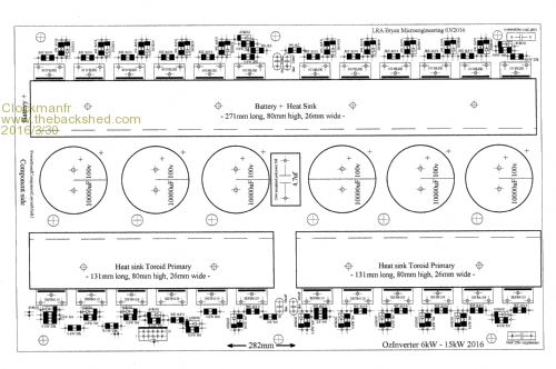
As you can see, the FET legs are deliberately splayed out. The copper double side boards should be double thickness ie 70 micron. The heat sinks and the caps down the centre are deliberate, as these are forced cooled when the board is pulling serious kW's. The board design is optimum for copper use, and boy do I need plenty of copper around those FET's. Might even need to beef that copper up, but will test first. Here is the drill mask with some dimensions. 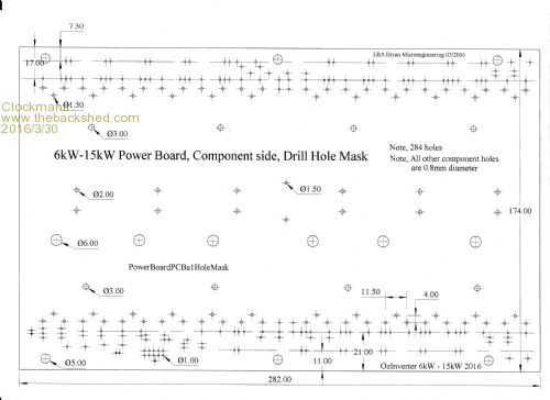
Everything is possible, just give me time. 3 HughP's 3.7m Wind T's (14 years). 5kW PV on 3 Trackers, (10 yrs). 21kW PV AC coupled SH GTI's. OzInverter created Grid. 1300ah 48v. |
||||
| Clockmanfr Guru Joined: 23/10/2015 Location: FrancePosts: 437 |
Just so you can see what your getting involved with.... Top board Mask..... 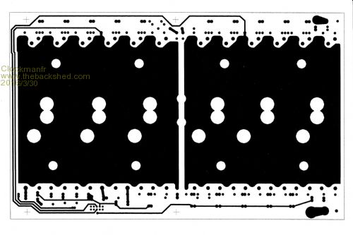
And under board mask.....this is a Mirror as it fits on the underside from the underside. 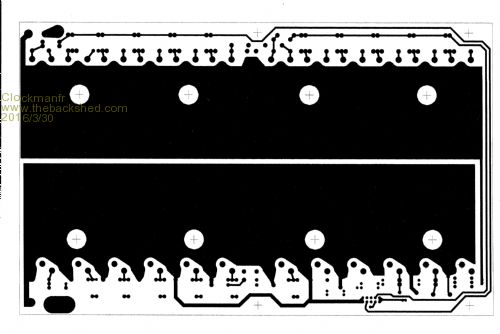
EPS files are okay and look reasonable. I also have both side pad tin masks, and silk screen mask. The idea is that these boards just fit onto sheets of A4 thermal transparencies. I will do exact copies sizes at high res of each mask, and put them as a pull out in in the Book. "Making a Low cost, simple and robust 6kW, 50HZ Pure Sine Wave, 48vdc to 230vac, INVERTER". You get a book you get the full size PCB masks. These can then be copied onto thermal transparencies at your local copy shop with a laser printer and then heated onto the PCB for etching, and then other stages. But it now seems folk want their PCB's made.. Everything is possible, just give me time. 3 HughP's 3.7m Wind T's (14 years). 5kW PV on 3 Trackers, (10 yrs). 21kW PV AC coupled SH GTI's. OzInverter created Grid. 1300ah 48v. |
||||
| Frank N. Furter Guru Joined: 28/05/2012 Location: GermanyPosts: 1141 |
Hi Clockmanfr, did I really understand that you are looking for a tool which converts DXF to Gerber? Try Target3001 I used successfully this program (full-version) to convert DXF to Gerber... Frank |
||||
| Clockmanfr Guru Joined: 23/10/2015 Location: FrancePosts: 437 |
Thanks Frank, It certainly looks promising, and a 300e price tag is not so bad. I will let you know how I get on, gulp! If nothing else at least it gives me a base file to work with..... This is from Target3001........................ CAD formats EAGLE and Protel 98/99/SE/Altium/Protel-DXP files can be imported to TARGET 3001! that means, the proprietary project files of the mentioned systems can be converted to the *.T3001 format. TARGET 3001! files also can be converted to EAGLE. In case you should need only subsets of project data you might import parts of your layout like a "painting" to TARGET 3001! that means you would get a plane vectorgraphics in TARGET 3001! lacking PCB informations (layer, pad properties, signal etc.). Conversions towards DXF, EPS... keep data less at last than the original file. Direct converters from other CAD systems to TARGET 3001! as well as the export to other CAD Systems from TARGET 3001! currently are not planned. The reasons are as follows: The development of a converter is very laborious and costly because the documentation ALWAYS is incomplete. The consequence is, that the other system mut be inspected properly which is time consuming (Reverse Engineering). In case an ASCII format is not available, a conversion is nearly impossible. The result is ALWAYS a non 100% converter! Other CAD-Systems have import filters for different other CAD systeme, but 100% conversion you'll only hear from the marketing departments. The converters are programmed only up to a certain grade of coverage because otherwise the cost of development are inadequate. Approximations are unavoidable. A certain pad form e.g. which is not available in the other system gets exchanged by the "worst case" alternative. Other CAD-Systems receive development which mostly is not documented. Maybe you can receive a conversion without mistakes but often it will be not complete... Everything is possible, just give me time. 3 HughP's 3.7m Wind T's (14 years). 5kW PV on 3 Trackers, (10 yrs). 21kW PV AC coupled SH GTI's. OzInverter created Grid. 1300ah 48v. |
||||
Grogster Admin Group Joined: 31/12/2012 Location: New ZealandPosts: 9985 |
Can you link to the inverter project? Smoke makes things work. When the smoke gets out, it stops! |
||||
| Clockmanfr Guru Joined: 23/10/2015 Location: FrancePosts: 437 |
Hi Grogster, Mostly here..... http://www.fieldlines.com/index.php/topic,148717.27.html and.............. http://www.fieldlines.com/index.php/topic,148827.0.html and ........... http://www.thebackshed.com/forum/forum_posts.asp?TID=8220&PN=1&TPN=1 and ........... http://www.thebackshed.com/forum/forum_posts.asp?TID=8220&PN=1&TPN=1 There are other links in, like the OzInverter Arduino WEB interface, etc and my post on these Power Boards, which got nasty. Everything is possible, just give me time. 3 HughP's 3.7m Wind T's (14 years). 5kW PV on 3 Trackers, (10 yrs). 21kW PV AC coupled SH GTI's. OzInverter created Grid. 1300ah 48v. |
||||
| Frank N. Furter Guru Joined: 28/05/2012 Location: GermanyPosts: 1141 |
@Clockmanfr: You should try the free version of Target3001. You can import (and export) many formats which are unlisted: 
You can import DXF and Gerber, you can export to STEP... Imported DXF or Gerbers are not enumerated as pins - so it should be possible to import DXF and export it as Gerber... ...and the "V18 discovery " 250 pin version is free! Frank |
||||
| Clockmanfr Guru Joined: 23/10/2015 Location: FrancePosts: 437 |
Many thanks Frank. Yes I have spent all morning checking Target version 18, and it looks good. If nothing else I am hoping that this software will let me sort out any DXF conversion problems. I have just purchased the 1 user licence, commercial use. I am only doing 2 boards, but folk want to buy them ready made with the book. So being honest. It only cost me �142, Sale On, and as I do not have any PCB software, you never know. If any of you are interested the Book is similar to my previous Making a 2kW Solar Tracker publication http://www.echorenovate.com/new-book---make-a-solar-tracker.php . Robust, simple and importantly cost effective. We are a not for profit here at http://www.echorenovate.com/ and the book is cost at Printing, its colour, with loads of photos, drawings etc 76 pages, A4 size, and P+P any where within reason in the World. This New OzInverter, in my opinion and others that have built them, Is very important. Its robust, uses little standby power, gives 6kW to 15kw if your batteries can take it, its simple and very cost-effective, about �600. If you have some electrical abilities, common sense, and sufficient skills, then they could be made anywhere on this Planet. You make the special Toroid, cooling system, AC electrics, 48v DC electrics. Control Board and Power Board, connect it up properly, install it properly....... Its all in the Book. So rather than sitting on the project, I am getting it out there...... Everything is possible, just give me time. 3 HughP's 3.7m Wind T's (14 years). 5kW PV on 3 Trackers, (10 yrs). 21kW PV AC coupled SH GTI's. OzInverter created Grid. 1300ah 48v. |
||||
| Clockmanfr Guru Joined: 23/10/2015 Location: FrancePosts: 437 |
Hi Frank, I downloaded the free version, the version I ordered will come in the post in the next couple of weeks. 
The freeware version took my DXF files and converted it to a lined, Polygram, and holed layout, with each entity being recognised by the Target software and at scale. The tracks will have to be re-laid at the correct thickness, pads, will need re-laying and areas will need filling, but in general the software is at least seeing the DXF, so that's good. I find Target is clunky and not laid out for folk like me. Line size, pad size, drawing tools etc, are not intuitive as I would like. However getting the now saved Target file to a gerber file is complicated to say the least. How do you do it please?. I also tried Sprint-Layout 6. Interestingly that's a reasonable good drawing system with line sizes, pad sizes, layers etc relatively easy to operate quickly and easy to adjust each settings without chasing around the screen. I tried importing a bitmap image but sadly it doesn't come in at scale size. I will probably use this software to layout the Control Board though. Everything is possible, just give me time. 3 HughP's 3.7m Wind T's (14 years). 5kW PV on 3 Trackers, (10 yrs). 21kW PV AC coupled SH GTI's. OzInverter created Grid. 1300ah 48v. |
||||
| MicroBlocks Guru Joined: 12/05/2012 Location: ThailandPosts: 2209 |
@clockmanfr, If you want me to give it a go then you can email the pdf and eps files to: 
Microblocks. Build with logic. |
||||
| Clockmanfr Guru Joined: 23/10/2015 Location: FrancePosts: 437 |
Hi MicroBlocks. And Thanks. I have a very slow French Satellite system here, so my emails may be slow for me to send. There are 10 files, PDF & EPS 6 of the 10 are actual PowerBoard PCB making Masks. the other 4 are 2 with further Info, and a Mirror the underside copper track mask and a Mirror underside solder pad mask. Hopefully you should get them all in about 10 hours time. Thanks again. Everything is possible, just give me time. 3 HughP's 3.7m Wind T's (14 years). 5kW PV on 3 Trackers, (10 yrs). 21kW PV AC coupled SH GTI's. OzInverter created Grid. 1300ah 48v. |
||||
| vegipete Guru Joined: 29/01/2013 Location: CanadaPosts: 1182 |
You can change the DPI setting in the 'Scanned Copy...' dialog to adjust the scale. And change the X and Y offsets to shift it around. Visit Vegipete's *Mite Library for cool programs. |
||||
bigmik Guru Joined: 20/06/2011 Location: AustraliaPosts: 2981 |
Hi Clockman, Can you attach a DXF file of one side I can try a convert to gerber with Autotrax DEX (it has a DXF import but I have never tried it).. Or can you point me to a direct link where I can download one? Kind Regards, Mick Mick's uMite Stuff can be found >>> HERE (Kindly hosted by Dontronics) <<< |
||||
| Frank N. Furter Guru Joined: 28/05/2012 Location: GermanyPosts: 1141 |
Hi Clockmanfr, IBF sends the program normally via Email + sends the program with the post on DVD (after receiving money). If you have problems with thickness of your lines, please check your DXF files - there are often problems with DXF files in other programs... Can you maybe use another DXF export function with your program??? It's relative simple to convert DXF in Gerber: - create a new job with board only (without circuit) - import DXF (you have many import functions) - you can export to Gerber with: - Files - In-/Output-Formats - Production - (X-)Gerbers ...or press simply F11 - specify your folder and press "Start" Let me know if I can help you! Frank |
||||
| Clockmanfr Guru Joined: 23/10/2015 Location: FrancePosts: 437 |
Hi vegipete. Yes I tried that but the res got real bad at half size. Its a big board. But I can see the function is usefull. BigMic, Dax DXF are AutoCAD format only, so the Dax is tweeted to function with there software. My DXF just come out blank. DXF files I send to Metal Laser cutters, engineering milling folk etc are no probs in the engineering world. Heres a Zip DXF of the top mask. Target shows this and there is functionality. 2016-04-01_074221_ZipFile.zip Thanks Frank, I will let you know of my adventurers. Here we go..... I have just had an email saying that my Target software is being sent to the USA.! There European site is strange and when I used it all I saw was German. So I purchased in English, what a mistake to make. I think folk with fast internet speeds take it for granted that everyone else is....... Everything is possible, just give me time. 3 HughP's 3.7m Wind T's (14 years). 5kW PV on 3 Trackers, (10 yrs). 21kW PV AC coupled SH GTI's. OzInverter created Grid. 1300ah 48v. |
||||
| bigmik Guru Joined: 20/06/2011 Location: AustraliaPosts: 2981 |
Hi Clockman, At first I thought it worked perfectly... Import of DXF into AutoTrax 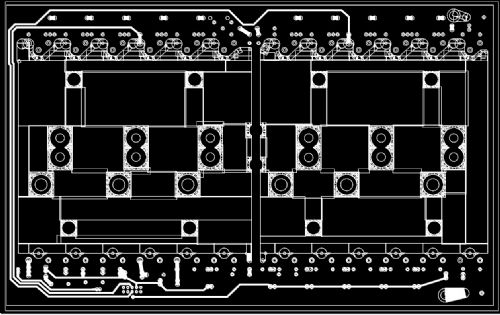
But then I found that Autotrax DEX imported into the DOCUMENTATION layer which doesnt actually get generated in the Gerber prints.. There is one other possibility.. We can convert to a picture format and DEX will allow that to be imported onto the copper ... I think... It is used to add a logo or other image but I do not think there is a size restriction. I will have a play, Mick Mick's uMite Stuff can be found >>> HERE (Kindly hosted by Dontronics) <<< |
||||
| Frank N. Furter Guru Joined: 28/05/2012 Location: GermanyPosts: 1141 |
Hi Clockmanfr, this is your DXF file, imported by Target, exported as Gerber and viewed with GC-Preview: 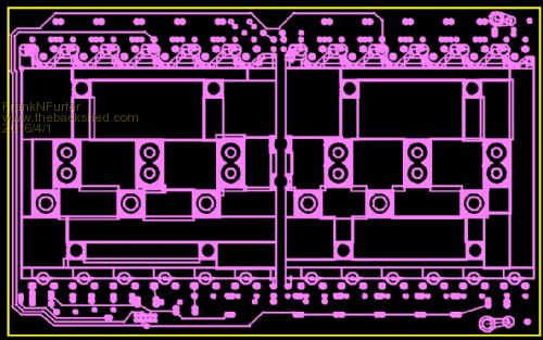
It seems to be a problem that your tracks are created with many fine lines... Your problems with the IBF site are strange - you can change your language to French, English or German... Frank |
||||
| Clockmanfr Guru Joined: 23/10/2015 Location: FrancePosts: 437 |
Thanks for looking bigmik. Hi Frank. Yes that's what I get, regards all the fine lines, its CAD entity blocks that define an area where you want a colour change. The way I use it is rough, dirty and quick to keep it a simple drawing without getting the layers mixed up. However for future reference I can clean those perimeter lines up and just use one line and fill. Not sure about those big holes though. Target see's all those lines perimeters from the DXF and what's better if you click on them in Target you can manipulate them, I think?. Grid will need redefining on the TARGET redraw, I normally set it at 0.25mm. So is it possible to redefine the big areas of copper and fill within Target before going to Gerber? Can we resize the lines to correct size? Obviously, I wont get this software for a while so hence me asking. If you zoom in on the Gerber file, how are the track lines,? they should be 1mm wide, 2mm wide between close pads. The French servers are blocking access to some sites and I have to use VPN. At present on my Mail I have this...... 
Everything is possible, just give me time. 3 HughP's 3.7m Wind T's (14 years). 5kW PV on 3 Trackers, (10 yrs). 21kW PV AC coupled SH GTI's. OzInverter created Grid. 1300ah 48v. |
||||
| Page 1 of 2 |
|||||
| The Back Shed's forum code is written, and hosted, in Australia. | © JAQ Software 2026 |
