
|
|
Forum Index : Microcontroller and PC projects : SSD1963 Compatability
| Page 1 of 2 |
|||||
| Author | Message | ||||
| Phil23 Guru Joined: 27/03/2016 Location: AustraliaPosts: 1667 |
Hi all, Ordered this screen a week or so back. Planning to playing with it on a MM+ with this Neither have arrived yet, but wondering if they are compatible? Resistive or Capacitive touch? Links the seller provided for specs don't seem to work. Cheers |
||||
disco4now Guru Joined: 18/12/2014 Location: AustraliaPosts: 1130 |
The LCD is similiar to one I have,resistive touch with the correct decoder chip installed. Should be OK. The SnadPIC is used by many on here as an MM2+ but you need to order with a 20 MHz crystal in lieu of 8MHz and with the MX470 chip. Just mention Micromite when ordering. If you did not ask for 20MHz you can probably change the crystal over. Regards Gerry F4 H7FotSF4xGT |
||||
| Phil23 Guru Joined: 27/03/2016 Location: AustraliaPosts: 1667 |
From their drop down option I chose "PIC32MX470F512L", which currently shows as out of stock. Is that the correct option? Or do I still need a different crystal? If so, where's a good place to grab one quickly here in Aus? Thanks Phil |
||||
| disco4now Guru Joined: 18/12/2014 Location: AustraliaPosts: 1130 |
Pretty sure you will need to 20MHZ crystal RS components online have some 20Mhz SMD crystals.e.g RS Components 20MHz I measured the size on my board, its about 3.0mm x 2.5mm and surface mount. The load resistors required for this one seems to be 15pF, the circuit diagram indicates 22pF are currently in place so not sure if you need to change them. RS Components deliver online orders free. Picture of back of board. 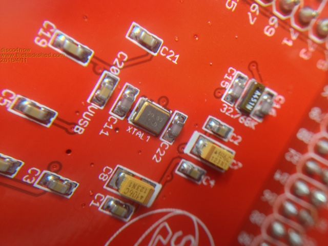
Someone that's done the change themselves might chime in with more info. Regards Gerry. F4 H7FotSF4xGT |
||||
| Phil23 Guru Joined: 27/03/2016 Location: AustraliaPosts: 1667 |
LCD Panel arrived 1/2 an hour after my last post. Haven't tried to lookup any data for it just yet, but here's a couple of pics. 
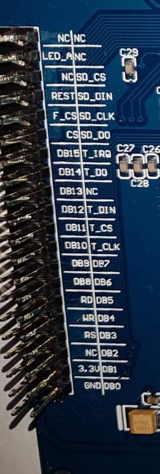
Someone might instantly recognise it. Cheers Phil |
||||
| paceman Guru Joined: 07/10/2011 Location: AustraliaPosts: 1329 |
I have one of those Phil, it should be fine with the SnadPic board (with the correct Xtal). You'll have a lot of pins to connect up, I use mine on one of Matherp's 64 pin 'Ultimate Backpack" boards which has a header already wired for it. There are a few points you should check especially re the backlight control - see the last few posts on this thread which is about the 4.3" 480x240 board but it's applicable to your 5" 800x480 which uses the same ILI1963 controller. In case you don't already have it, here's the schematic for your display. 2016-04-11_053209_Schematic.pdf Greg |
||||
| Bill7300 Senior Member Joined: 05/08/2014 Location: AustraliaPosts: 159 |
Bill |
||||
| Bill7300 Senior Member Joined: 05/08/2014 Location: AustraliaPosts: 159 |
Those load "resistors" are actually capacitors, Gerry, hence the 15pF or 22pF - but I suspect you already know that? Cheers Bill Bill |
||||
| Phil23 Guru Joined: 27/03/2016 Location: AustraliaPosts: 1667 |
The original listing does state an 8MHz Crystal. Ordered a couple from RS earlier. Hope I'm not biting off more than I can chew with this. Crystal sounds small for someone with only an old TC201 iron. Sound like it's way more complex to interface that the MM LCD Backpack. |
||||
| Phil23 Guru Joined: 27/03/2016 Location: AustraliaPosts: 1667 |
Is that something I'm able to source somewhere? Did a quick search but no hit. Thanks. Phil. |
||||
| paceman Guru Joined: 07/10/2011 Location: AustraliaPosts: 1329 |
You'll need to PM MatherP to see if he has one available, I think there were only 10 or so made. Peter built two versions for the Micromite Plus i.e. running on MX470 chips. One for the 44 pin chip and one for the 64 pinner, I have the latter. As far as I know there isn't one (at this stage) set up for the 100 pinner you're looking to use except the SnadPic board (or just a standard 100 pin breakout). Neither of these has a header set up for the parallel 40 pin ILI1963 panel. Greg |
||||
| paceman Guru Joined: 07/10/2011 Location: AustraliaPosts: 1329 |
Phil, You probably already know this but just correcting my earlier post. At 3:34pm I said "(with the 20 MHz xtal)". That's true but as 'disco4now' noted earlier you of course also have to have the MX470 processor (PIC32MX470F512L-120/PF or PIC32MX470F512L-I/PF), not the MX795 that is standard on the SnadPIC board if you intend to use that board. Greg |
||||
| Phil23 Guru Joined: 27/03/2016 Location: AustraliaPosts: 1667 |
Received the board today, It has an 8.0MHz Oscillator on it. Ordered the 20Mhz ones mentioned above, but they are much smaller. This one is 5 x 3mm roughly. Does this one look like the correct replacement? 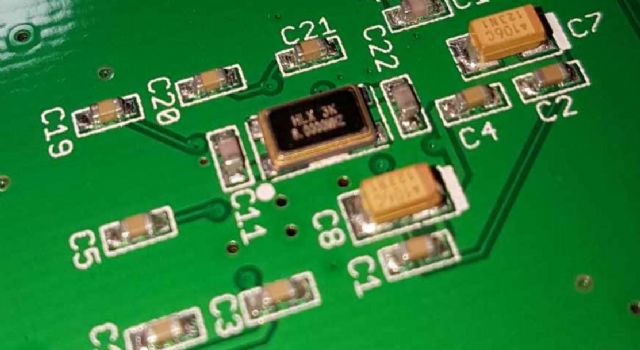
Thanks. Phil |
||||
| disco4now Guru Joined: 18/12/2014 Location: AustraliaPosts: 1130 |
Hi Phil, I think I may have given you some misinformation on my first posting of a link to a suitable crystal.It seems I pointed out a crystal oscillator unit where as you need just a crystal. The 4 pin SMD crystals seem to all have the crystal between 1 and 3, the other pins for shielding I guess. The board seems to have 4 pins, so I guess you need a 4 pin one. The one I originally linked to and the one you link to are crystal oscillator units, these take VCC + GRN and output the 20Mhz. This is not what is required here. The link below is for a 4 pin crystal. I am guessing this would do the job and that the pin layout on the SMD crystals are a standard. 20MHz SMD Crystal Someone who really knows may confirm? Regards Gerry F4 H7FotSF4xGT |
||||
palcal Guru Joined: 12/10/2011 Location: AustraliaPosts: 2039 |
The crystal on the board is similar to the 8MHz on on your board, it has the marking FXC 20.0 and XU06. The best bet would be to email the guy at SnadPic and I am sure he will be happy to set you right. Paul "It is better to be ignorant and ask a stupid question than to be plain Stupid and not ask at all" |
||||
| Phil23 Guru Joined: 27/03/2016 Location: AustraliaPosts: 1667 |
So the one I mentioned above, from RS components may not be correct? Ordered one today on the off chance.... Thanks |
||||
| Phil23 Guru Joined: 27/03/2016 Location: AustraliaPosts: 1667 |
Hi All, Received the crystal I ordered today. Is someone able to confirm it is correct? Wasn't 100% sure. Also any advice on replacement would be appreciated. Only have a TC201 Weller, 0.8mm my smallest tip. 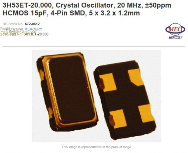
Anything else? Someone mentioned the value of the caps may differ. Thanks Phil |
||||
| disco4now Guru Joined: 18/12/2014 Location: AustraliaPosts: 1130 |
Hi Phil The datasheet for what you have is here. See it has VCC ,GRN ,control and Output for the 4 pins. datasheet As I posted above I think this is not what you want. You just need the crystal.i.e. Crystal If you scroll down on the above link you see that even though it has 4 tabs ,it just has the crystal between tabs 1 and 3. For removal, I would used a bit of solder on the tip of the iron, and place against each pad in turn while slightly levering up. Repeat for otherpads. Once off, clean up the pads. When replacing, use plenty of flux and solder will wick underneath the pad ok. You could take it off and poke around with a meter between the pads to verify what you have looks like what is taken off. Pretty sure you need to get just the crystal. Regards Gerry F4 H7FotSF4xGT |
||||
| Phil23 Guru Joined: 27/03/2016 Location: AustraliaPosts: 1667 |
So I finally got the correct Crystal (I hope) and replaced the 8MHz one with a 20MHz. Presume I also have to remove the 32.768k one as well? 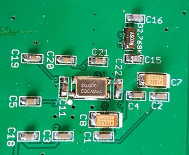
Is that all then good to go? Someone mentions capacitors.... Thanks Phil |
||||
| Bill7300 Senior Member Joined: 05/08/2014 Location: AustraliaPosts: 159 |
Coming into the discussion totally cold but I would imagine the 32.768MHz crystal is for a Real Time Clock and therefore needn't be removed? There will be two padding capacitors with the crystal but these would only require changing if the 20 MHz rock's requirements differ from the 8 MHz rock's. Do you have specs on the 20 MHz's requirements? Bill |
||||
| Page 1 of 2 |
|||||
| The Back Shed's forum code is written, and hosted, in Australia. | © JAQ Software 2026 |
