
|
|
Forum Index : Microcontroller and PC projects : Introducing the Micromite Extreme Edition
| Page 1 of 3 |
|||||
| Author | Message | ||||
| matherp Guru Joined: 11/12/2012 Location: United KingdomPosts: 11424 |
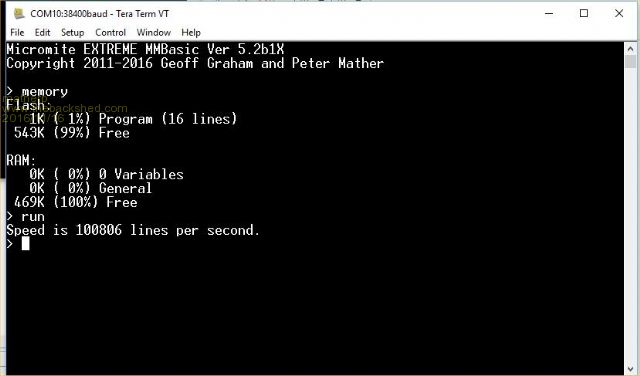 It had to be done  Attached, with Geoff's approval, is a hex file for the Micromite code V5.2 to run on a PIC32MZ chip. The PIC32MZ runs at 198MHz and has 512K RAM. It also has hardware floating point and 12-bit analog to digital convertors. The MZ doesn't need a VCAP just good decoupling at each power input. Early indications are that MMBasic runs more than twice as fast as on the MX470 as well as having lots of extra memory. 2016-11-16_110646_MicromiteExtremeV5.2b1X.zip All 5.2 Micromite Plus functionality has been included (i.e.including SDcard, USB etc.) and has been tested at various stages of development but this is a first beta so...... The code has been developed on a PIC32MZ2048EFG064 (huge thanks to Kiiid for the development board) but should work on a PIC32MZ2048EFG100, PIC32MZ2048EFH064 and PIC32MZ2048EFH100 Next steps are to integrate any new 5.3 functionality and bug fixes. Then I'm going to look at converting all floating point operations to DOUBLE using the power of the hardware floating point. Also the chip has hardware random number generation which should be used. Finally, the chip is capable of running a VGA monitor like the Maximite but getting that running in a Harmony environment might be tricky  The crystal required is 12MHz Pinout for the 64 pin chip is currently as follows but the allocation of special functions may change slightly in future 1 Analog/Digital/SSD1963-D5 2 Analog/Digital/SSD1963-D6 3 Analog/Digital/SSD1963-D7 4 Analog/Digital/SPI2-CLK 5 Analog/Digital/SPI2-OUT 6 Analog/Digital/SPI1-OUT 7 VSS 8 3.3V 9 MCLR/5V 10 Analog/Digital/PWM-1A 11 Analog/Digital/COM2-TX 12 Analog/Digital/PWM-2A 13 Analog/Digital/COM2-RX 14 Analog/Digital/KYBD-CLK ' Note: not 5V so use resistor 15 Analog/Digital/KYBD-DAT ' Note: not 5V so use resistor 16 Analog/Digital/COM3-TX 17 Analog/Digital/COM3-RX 18 Analog/Digital 19 AVDD 20 AVSS 21 Analog/Digital/COM3-RX 22 Analog/Digital 23 Analog/Digital/COUNT 24 Analog/Digital/SSD1963-WR 25 VSS 26 VDD 27 Analog/Digital/SSD1963-RS 28 Analog/Digital/SSD1963-RESET 29 Analog/Digital/PWM-1B 30 Analog/Digital/PWM-2B 31 XTAL: 12MHz 32 XTAL: 12MHz 33 USB-VBUS 34 USB-VUSB 35 VSS 36 USB-D- 37 USB-D+ 38 Digital/COM1-EN 39 VDD 40 VSS 41 DIGITAL/5V/COM1-RX 42 DIGITAL/5V/COM1-TX 43 DIGITAL/5V/I2C-SDA 44 DIGITAL/5V/I2C-SCK 45 DIGITAL/5V 46 DIGITAL/5V/COUNT 47 DIGITAL/COUNT/IR 48 DIGITAL/PWM-1C 49 DIGITAL/5V/SPI1-CLK 50 DIGITAL/5V/SPI1-IN 51 DIGITAL/5V/SPI2-IN 52 DIGITAL/5V/COUNT 53 DIGITAL/5V 54 VDD 55 VSS 56 5V/Console-TX/COM4-TX 57 5V/Console-RX/COM4-RX 58 DIGITAL/5V/SSD1963-D0 59 VSS 60 VDD 61 DIGITAL/5V/SSD1963-D1 62 DIGITAL/5V/SSD1963-D2 63 DIGITAL/5V/SSD1963-D3 64 DIGITAL/5V/SSD1963-D4 |
||||
| sagt3k Guru Joined: 01/02/2015 Location: ItalyPosts: 313 |
Great .... compliments  |
||||
| WhiteWizzard Guru Joined: 05/04/2013 Location: United KingdomPosts: 2977 |
This is brilliant work guys (even though you've now ruined my kids Christmas!!)A few early/immediate questions: 1> Does it still run a Console connection too on COM1 (Tx and Rx)? 2> What kind of current (mA's) does this beast pull? (assume nothing attached so comparisons can be made with the figures in Geoff's manuals) 3> Could you ping me a link to a board / circuit if you have one available  4> Anything not working that 'should be' from the normal v5.2? 5> IF you get the VGA resolved, would it just display the 'console output' OR would it be possible to display all MMBASIC graphics/GUI stuff (i.e. duplicate the contents of a SSD TFT)? Can't wait to try this . . . . . WW |
||||
| matherp Guru Joined: 11/12/2012 Location: United KingdomPosts: 11424 |
Yes, COM4 same as MX470, see pinout for connections 2> What kind of current (mA's) does this beast pull? (assume nothing attached so comparisons can be made with the figures in Geoff's manuals) Just measured at 3.3V 135mA = c0.5W, no peripherals This one should work - not tested Probably, but not by design TBD |
||||
| sagt3k Guru Joined: 01/02/2015 Location: ItalyPosts: 313 |
Hi matherp I want create a PCB asap ... Can you public a schematic with essential components? Thanks Saht3k |
||||
| MicroBlocks Guru Joined: 12/05/2012 Location: ThailandPosts: 2209 |
Wouldn't supporting VGA not eat up all(most) serial/i2c/spi ports and lots of RAM memory? My vote would be to at least make it completely optional as the solutions with LCD screens is already working good. Microblocks. Build with logic. |
||||
| matherp Guru Joined: 11/12/2012 Location: United KingdomPosts: 11424 |
These is no schematic needed. Just put 3.3V on all VDD pins including AVDD and pin 34(USB-VUSB). Connect 0V on all VSS pins including AVSS. Use lots of decoupling for each pin. Pull MCLR high via a 10K resistor. Use a 12MHz external oscillator (IMPORTANT not a crystal) connected to pin 31, leave pin 32 unconnected. Most connections are as per the MX470. i.e. SPI2 used for SDcard, Touch and ILI9341 (NOTE pin 51 is used for SPI2-IN and NOT pin-47). Pinout for SSD1963 as per the pinout above USB, if you want to use it, connect incoming 5V to pin 33, D+ and D- as per pinout, GND connected, incoming USBID not connected It can be turned on and off on the Maximite. Turning it off frees the memory. The pins on the Micromite would only be allocated if turned on |
||||
kiiid Guru Joined: 11/05/2013 Location: United KingdomPosts: 671 |
Good one Peter  I have a MZEF64 board (new revision) currently in manufacturing. Here is what it looks like (those grey things are actually headers, don't mind the poor render). And the schematic, which is based on the original MZEF64 which you have. A full port of MMBasic NOT based on Harmony but on PLIB is done (credit to Spas for the huge volume of work on that port) and will be out to Geoff for approval in the next day or two. 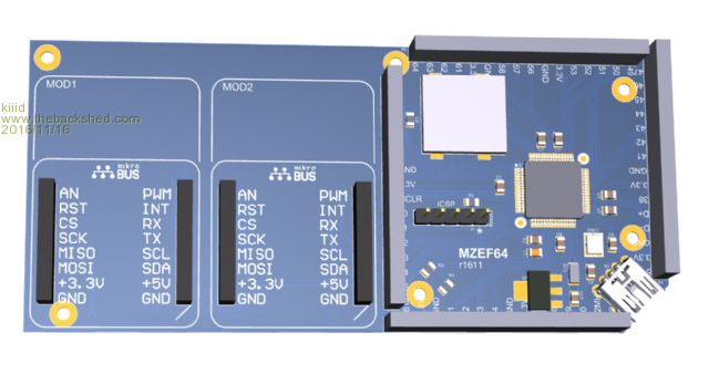 2016-11-16_122945_MZEF64.pdf http://rittle.org -------------- |
||||
| WhiteWizzard Guru Joined: 05/04/2013 Location: United KingdomPosts: 2977 |
Peter, Thanks for your responses, and the link. (I totally missed the COM4 pinout stating 'console'  ) )Would you consider using all 16 SSD data signals on this beast? I seem to remember you commenting on only half the data lines being used in some previous post giving some 'limitation'. So raises the question that if you were to use all 16, would it speed up (or slow down!) the screen 'drawing' OR would it simply just give more colours? Or possibly this is not a consideration due to integrating with existing MMBASIC. Will try and make a quick PCB here assuming there are no gotcha's. Thinking of just expanding all pins out to four 16 pin headers with decouplers local to power pins, crystal + caps, then jumping appropriate I/O pins to a TFT and Grogster's SD add-on PCB. |
||||
| WhiteWizzard Guru Joined: 05/04/2013 Location: United KingdomPosts: 2977 |
|
||||
| sagt3k Guru Joined: 01/02/2015 Location: ItalyPosts: 313 |
Thank very interesting. Thanks Sagt3k |
||||
| WhiteWizzard Guru Joined: 05/04/2013 Location: United KingdomPosts: 2977 |
Would the excellent features of the PIC16F1455 work with this too for updates? |
||||
disco4now Guru Joined: 18/12/2014 Location: AustraliaPosts: 1126 |
Hi Peter, I though you had been a bit quiet. Great work! What is the situation with CFunctions with this. If you order a snapic board would you need to ask for the 12MHz crystal in lieu of 24MHz. Regards Gerry F4 H7FotSF4xGT |
||||
| sagt3k Guru Joined: 01/02/2015 Location: ItalyPosts: 313 |
Hi to eserybody Now it might be interesting integrate code for the most common modules as: - wifi esp8266 - mpu6050 - bmp/e280 or if possible to load/integrate subs from uSD to append in the editor etc... I suppose to do a porting library from arduino.... create .bas in the uSD and load/unload with #include etc by ibtegrated editor... Etc? Thanks |
||||
| isochronic Guru Joined: 21/01/2012 Location: AustraliaPosts: 689 |
Welcome to the MZ zeitgeist ! I am getting similar speed increases, 160 k lines /sec for simple loops ( carefully optimised though  ). ).Are you using Harmony or a bespoke PLIB? I have revised my 100 pin MZ pcb and have had some made but I haven't built one up yet...I could make the gerbers available I guess. It would be good to maintain some compatibility . Microchip also have some cheap dev boards one for MZ - dev board there is also a cheap 470 one. |
||||
| matherp Guru Joined: 11/12/2012 Location: United KingdomPosts: 11424 |
It could be done but not on the 64-pin chip so I think the Loadable driver approach is the best way of getting the extra speed on a 100-pin chip. As a USB/UART - yes; as a programmer - not yet tested They work based on limited testing. In theory they should be able to do floating point calcs direct but again not tested I don't understand this requirement. These all work perfectly in Basic what does including them in the firmware achieve except increasing complexity and adding to all regression testing? Harmony just for chip initialisation and USB "myplib" for everything else Everyone, please note my statement in the original post if you are designing a PCB |
||||
| panky Guru Joined: 02/10/2012 Location: AustraliaPosts: 1127 |
Great work Peter, Does your implimentation use a bootloader like the Maximite or is a PicKit 3 needed to load EMMBasic? Thanks for your great work and contributions, Doug. PS. Peter, do you have any plans to modify/update your backpack board you designed? That is a terrific little board especially for testing or just playing as it has connectors and support for all the TFTs from 2.4" to 8" Doug. ... almost all of the Maximites, the MicromMites, the MM Extremes, the ArmMites, the PicoMite and loving it! |
||||
| Bill7300 Senior Member Joined: 05/08/2014 Location: AustraliaPosts: 159 |
Wow! Waking up to see what is new in the Micromite world has become a daily treat for me. You blokes just never cease to amaze me, especially you Peter. Many many thanks. Bill |
||||
| JohnL Senior Member Joined: 10/01/2014 Location: SeychellesPosts: 128 |
$32 AU for the 100 pin microcontroller chip alone. http://au.element14.com/microchip/pic32mz2048efg100-i-pt/mcu-32bit-pic32mz-200mhz-tqfp/dp/2500473?ost=PIC32MZ2048EFG100& selectedCategoryId=&categoryId=800000000185&searchView=table&iscrfnonsku=false Better quality external crystal oscillator will set you back about another AU$5.00. + PCB + tons of decoupling caps and you still have to build it? All of this to run "dressed up" old quirky Basic language in 2016? If you really need interactive scripting language on the powerful microcontroller why not use much easier and exponentially more powerful up to date language like Python, or anything else (C , javascript, etc.) on SOC boards with proper multitasking operating system , built in WIFI, tons more memory and all other bells and whistles for less than $10? only one example. https://getchip.com/pages/chip Even full genuine Raspberry Pi and Beaglebones will cost less than this. [flame suit on] I guess hard core MMbasic fanboys will justify things differently. |
||||
| WhiteWizzard Guru Joined: 05/04/2013 Location: United KingdomPosts: 2977 |
Blimey JohnL - I recommend you change your component supplier if they're wanting to charge that much. Can get two PICs + oscillators + all decoupling caps for less than that price! Did I mention thats with them being delivered free, and within 24hours! My justification for wanting to use 'quirky Basic in 2016' is real simple: 'ease-of-use' (something systems people repeatedly like to overlook!) I could go on but . . . . |
||||
| Page 1 of 3 |
|||||
| The Back Shed's forum code is written, and hosted, in Australia. | © JAQ Software 2026 |
