
|
|
Forum Index : Microcontroller and PC projects : PicoMiteHDMIUSB motherboard reference design
| Author | Message | ||||
| matherp Guru Joined: 11/12/2012 Location: United KingdomPosts: 11698 |
Coming soon 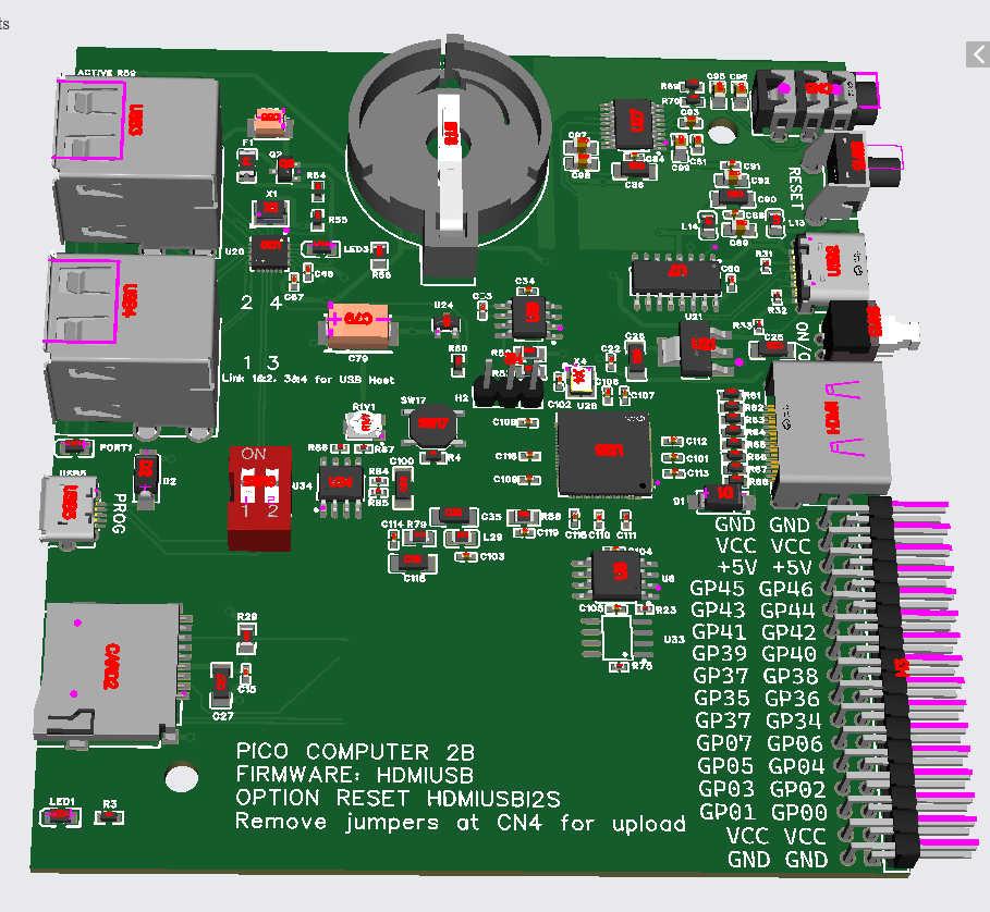 not routed yet and component placements may change but you get the idea |
||||
| lizby Guru Joined: 17/05/2016 Location: United StatesPosts: 3838 |
Nice. Your silk screen has GP37 twice. PicoMite, Armmite F4, SensorKits, MMBasic Hardware, Games, etc. on FOTS |
||||
| Mixtel90 Guru Joined: 05/10/2019 Location: United KingdomPosts: 8997 |
Nice. I like. :) Mick Zilog Inside! nascom.info for Nascom & Gemini Preliminary MMBasic docs & my PCB designs |
||||
| ManiB Senior Member Joined: 12/10/2019 Location: GermanyPosts: 159 |
It's worth the wait. Can JLCPCB mount the RP2350? Because I couldn't solder it on by hand. Edited 2025-03-05 02:15 by ManiB |
||||
| Amnesie Guru Joined: 30/06/2020 Location: GermanyPosts: 763 |
Yes, JLCPCB will do the assembly  Greetings Daniel |
||||
| ManiB Senior Member Joined: 12/10/2019 Location: GermanyPosts: 159 |
There you go, Peter, that's your ‘minor change’ ;) I don't know you personally, but now I can get a clear picture of you: ‘A professional with attention to detail’. I celebrate this board the more posts I read every day. I plan to document my experiences and make them available here on the board. I know this won't really impress you ‘old hands’, but if someone faces the same challenge in the future, it can be very useful. |
||||
| WhiteWizzard Guru Joined: 05/04/2013 Location: United KingdomPosts: 2991 |
@Peter, Are you using the exact same ‘adjustable DVDD’ circuit on this unit as you used on the DIL module? Great work (as always!!!!!) |
||||
| Volhout Guru Joined: 05/03/2018 Location: NetherlandsPosts: 6007 |
@Peter, - silkscreen text: "jumpers at CN4" refer to a switch ? - Would it be an option to add a buck/boost for the 5V ? You have suggested multiple times that a "good USB-C" cable is needed. Not for communications, but for voltage drop on the power conductors. A buck/boost convertor would guarantee adequate 5V for the attached 4 USB devices, even when the voltage on the USB-C drops to 4V. Something like this (but then put on the board, not as a module). With proper design you could even make this compatible with 12V/20V on USB-C (with a fast charger). 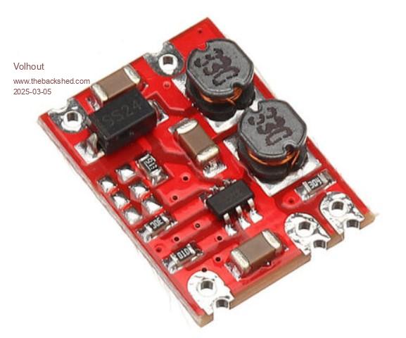 Volhout Edited 2025-03-05 18:46 by Volhout PicomiteVGA PETSCII ROBOTS |
||||
| matherp Guru Joined: 11/12/2012 Location: United KingdomPosts: 11698 |
Yes Schematic ddf6cc27-0325-48cc-9c50-870099aae8e6.pdf Routed versions 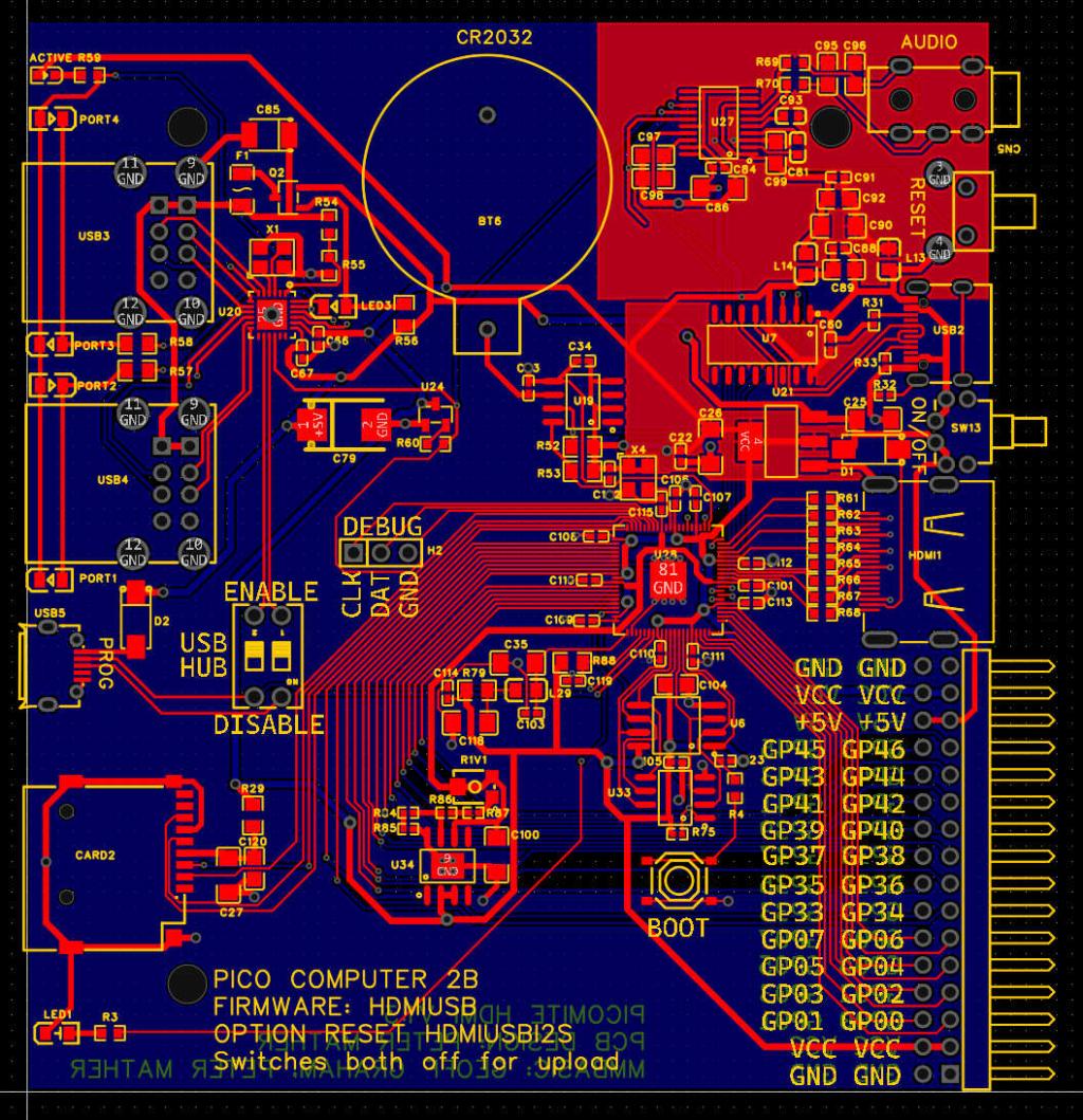 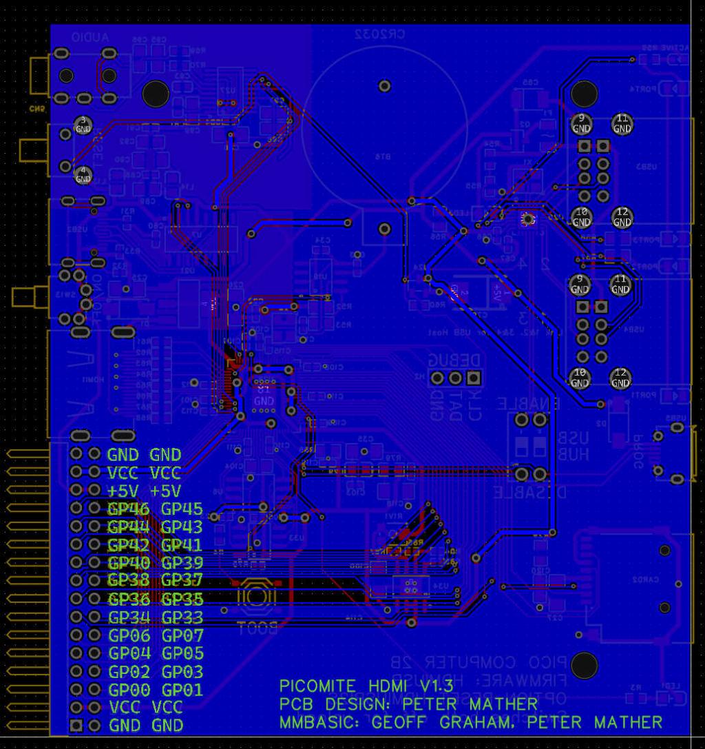 Edited 2025-03-05 18:57 by matherp |
||||
| PhenixRising Guru Joined: 07/11/2023 Location: United KingdomPosts: 2035 |
The excitement continues   |
||||
| Volhout Guru Joined: 05/03/2018 Location: NetherlandsPosts: 6007 |
Peter, It is nice to have adjustable DVDD, but when many are building this version, you may want to standardize on a value. In that case a bypass of R1V1 would be needed. For experiments R1V1 is great, but you do not want people playing with it to the extend that it can do more harm than good, or worst case destroy a chip. On the PCM5102: it has a charge pump build in (creating a negative voltage). It does that by chopping the 3.3V. Why do you power the chopper input pin to analog Vdd and analog ground ? It is the most noisy in the whole audio circuit. Is this what the datasheet tells you ? Volhout Edited 2025-03-05 20:16 by Volhout PicomiteVGA PETSCII ROBOTS |
||||
| WhiteWizzard Guru Joined: 05/04/2013 Location: United KingdomPosts: 2991 |
@Peter, What’s the functionality of SW17 please (Primary Flash enable?) |
||||
| matherp Guru Joined: 11/12/2012 Location: United KingdomPosts: 11698 |
The datasheet explicitly shows the charge pump with the same supply as the analog circuitry 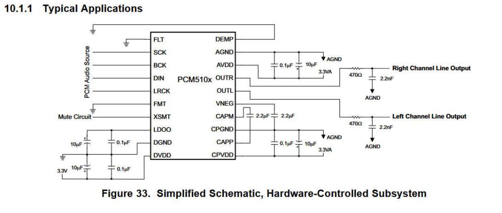 A final version can have a fixed DVDD but for the moment I need to be able to adjust it to tune the overclock. BOOT Edited 2025-03-05 21:02 by matherp |
||||
| PhenixRising Guru Joined: 07/11/2023 Location: United KingdomPosts: 2035 |
Hey Pete, Is there gonna be a 4th mounting hole or just the 3? |
||||
| Mixtel90 Guru Joined: 05/10/2019 Location: United KingdomPosts: 8997 |
With that size board I've managed with just two diagonal holes, even at 1.2mm thickness. I wouldn't worry too much. :) If you use 1.6mm board it won't flex at all without a hammer... Mick Zilog Inside! nascom.info for Nascom & Gemini Preliminary MMBasic docs & my PCB designs |
||||
| PhenixRising Guru Joined: 07/11/2023 Location: United KingdomPosts: 2035 |
Looking at stacking my own board with it but I don't like flex.  |
||||
| matherp Guru Joined: 11/12/2012 Location: United KingdomPosts: 11698 |
It will be back |
||||
| PhenixRising Guru Joined: 07/11/2023 Location: United KingdomPosts: 2035 |
Is that you Arnold?  |
||||
| Mixtel90 Guru Joined: 05/10/2019 Location: United KingdomPosts: 8997 |
@ Volhout I've just modified a 3V3 version of one of those little S09 buck/boost converters to 5V by changing the feedback resistor to 150K (I don't happen to have any 5V ones). I have it powering my PicoGAME HDMI with wireless keyboard, two generic gamepads and a SD card. Barely warm hanging in free air and the output voltage has barely dropped from the off-load voltage. 103mA drawn from a 12V supply to the convertor, 169mA at 7.5V. My little 300mA power supply is shutting down when I try lower voltages, which makes sense, I think. Watch out for a new "portable" design with 3-15V (well, that's what they say) input. :) Mick Zilog Inside! nascom.info for Nascom & Gemini Preliminary MMBasic docs & my PCB designs |
||||
| JohnS Guru Joined: 18/11/2011 Location: United KingdomPosts: 4358 |
Would it cope with 15.4V? Not for me, but some cars have a "12V" around there (from the charging circuit). John |
||||
| The Back Shed's forum code is written, and hosted, in Australia. | © JAQ Software 2026 |
