
|
|
Forum Index : Microcontroller and PC projects : Proto Board for the uMite 28
| Author | Message | ||||
bigmik Guru Joined: 20/06/2011 Location: AustraliaPosts: 2981 |
Lads, I have what I think we be the final Version. Please Appraise if you will SCHEMATIC 2014-04-14_022801_mmite.pdf OVERLAY 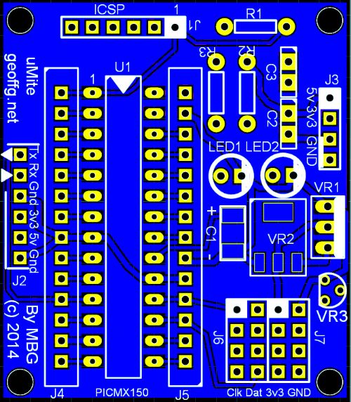
Now I have a question with I2C.. I have put 4 rows of pins for I2C on J6 and J7. I have put 3v3 as the voltage supply, should I instead make this 5V to supply the I2C devices.. (I have not personally had any direct experience with I2C) Regards, Mick Mick's uMite Stuff can be found >>> HERE (Kindly hosted by Dontronics) <<< |
||||
| Zonker Guru Joined: 18/08/2012 Location: United StatesPosts: 772 |
Sorry Gents, was away for awhile, spending the evening with the frends we helped move to the new apartment today... Anyway, I had the post sent by registered Air mail... Here is what the Itead response said about it... As far as I know, there were no extra fees added on... I hopes this helps...! |
||||
| MicroBlocks Guru Joined: 12/05/2012 Location: ThailandPosts: 2209 |
I have a SMD uMite board (37x46mm) where the pins are grouped and organised on a bus. This allows for a very easy connection to other boards by flatcable, vero strip board, etc. Also stacking will be an option. Mounting holes to firmly attach it. Programming can be done by a standard ICSP connector. A reset button for convenience. A USB-Serial is on a separate board (37x32mm) that easily connects to the mcu board (could be stacked also). You could also use one of your own USB-Serial if that is preferred. This USB-Serial uses the MCP2200. It can connect to the console pins of the uMite but also via the bus to the other serial port. It can use or route the power supply from the bus or USB to the mcu. Added feature is that under PC software control you would be able to reset the mcu. Two leds for RX and TX activity that canbe disabled to allow for less power usage. Via the bus you can connect multiple boards or use it next to a breadboard for easy prototyping, all of the the breadboard pins will be available allowing for a easier placement and wiring. I am waiting for the final release of the uMite before committing to a pcb as this board groups the pins and i don't want to have the risk that pins have added functionality on the last moment ending up with a sub optimal pcb. Here is the mcu pcb together with the usb-serial: 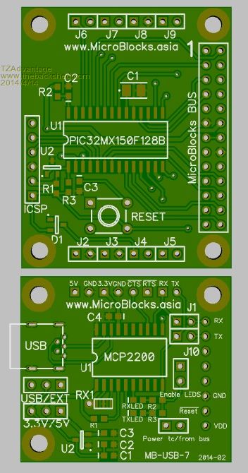
Microblocks. Build with logic. |
||||
| JohnL Senior Member Joined: 10/01/2014 Location: SeychellesPosts: 128 |
Board looks good except that I need PIC as DIP to go in to a socket for easy embedded repair/replacement. Let us know if you consider a DIP version. Some other PIC32MX150 alternatives boards and products, also ByPic Basic. http://www.ebay.co.uk/itm/Mini-Max-PIC32-RAD-Microcontroller -Development-Board-not-Arduino-/111310067105?pt=UK_BOI_Elect rical_Components_Supplies_ET&var=&hash=item5f87f9171f http://stores.ebay.co.uk/ByVac-Electronics/Microcontrollers- /_i.html?_fsub=936887010 |
||||
| Keith W. Senior Member Joined: 09/10/2011 Location: AustraliaPosts: 118 |
A Prototype Board for raw beginners? Geoff typically surprises us, me anyway. He often keeps something up his sleeve until he publishes or releases. We have not seen the Silicon Chip release yet. Will there be a surprise? Is there a prototyping board suggestion? I will be quite satisfied regardless Geoff. 
Eldest grandson is very excited after a demonstration of the Micromite controlling my staircase lights and wants his own development board, particularly when I edited the program while he watched. I have told him to wait for the S.C. release and Geoff�s article to set him going and to help bring his (Technician) father up to speed as they live at least an hour away. Andrew will require some peripherals on or with his board to hint at possibilities to explore. He has asked me many times about the LCD display that he found in the Manual. Resistors are likely required to keep the special smoke inside the chip and buffers/relays to a voltage suitable for motors. He insists that he can control his train set. Perhaps a mother board to carry Bigmiks board. He must learn about BASIC and programming which requires more than the Micromite Manual which is about MMBasic custom variations. That he starts learning using a Micromite not a PC program is OK and making the chip control something will be satisfying and he loves to tinker. MM Edit seems more suitable for a beginner than Teraterm. It gives Command Help, looks after program files and chip programming and connects in a way that simplifies the process. Perhaps it is too automatic for a beginner to appreciate what is happening. CircuitGizmos great Begmax.pdf contains a lot of information but is not specifically for the Micromite. I found a beginners text on the web, �Blast off With Basic� 1991 by Brian R. Page, and have downloaded �Just Basic� (www.justbasic.com). Can anyone suggest a text for a raw beginner that is not so much GW-Basic c/w graphics on a PC? Is anyone proposing to offer an expansion board? Perhaps a full Maximite would be a better start but we would have to wait for Geoff to update for it to be more Micromite like hardware capable. Starting Andrew (12 years) into programming is a new project. Keith W. |
||||
| WhiteWizzard Guru Joined: 05/04/2013 Location: United KingdomPosts: 2991 |
Hi John, The PCB that I designed for my 44-pin MicroMite Module is based on a DIP pin-out being just a little longer than a 40pin DIP IC (actual size is 68mmx22mm). It also gives a access to a total of 33 I/Os so it could open up more potential for you depending upon your actual design requirements. If you just populate the TQFP and caps on my low-cost PCB then this would create a ready-made plug-in module for easily embedding into your design. Simply use 2 x 22pin single row sockets on your PCB to make servicing a breeze. 
You can PM me if you need more information. |
||||
| MicroBlocks Guru Joined: 12/05/2012 Location: ThailandPosts: 2209 |
I am trying to make an all through hole version with the same footprint. Very tight but i should be able to pull it off. The reason for an all smd is assembly and overall height. With all smd parts it is just one time in the reflow oven. The connectors that you want to use can then be hand soldered. The connectors can be straight, angled or stackable. This will give the most flexible mounting options. The SMD components are lower in height (especially compared to a dip in a socket) and allows for stacking of boards. The boards are designed for easy proto type use AND mounting in a final product.If bus signals are used it would then also be possible to add interfaces, and upgrade boards giving a product a longer lifespan. Microblocks. Build with logic. |
||||
BobD Guru Joined: 07/12/2011 Location: AustraliaPosts: 935 |
Mick, You should give the option for both voltages. I believe some I2C devices must have 5 volts so limiting to 3.3 volts or vice versa may be inconvenient. Suggestion is to make the voltage jumper selectable or make both voltages available. |
||||
| vasi Guru Joined: 23/03/2007 Location: RomaniaPosts: 1697 |
Hi guys, About development boards, I never liked fixed configurations and connections to the microcontroller on board. Fortunately, there are some who started to make boards with the highest level of configurability. So, before jumping into designing a development board for MicroMite, look at these inspiring images: 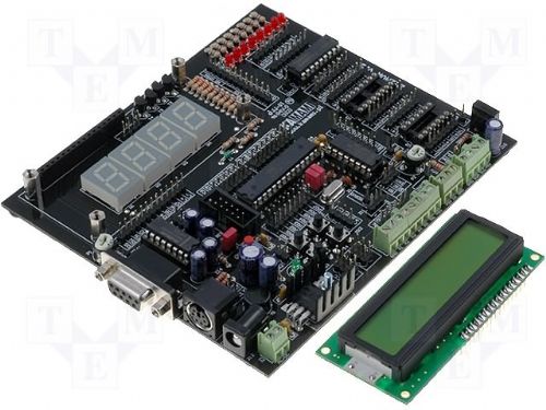
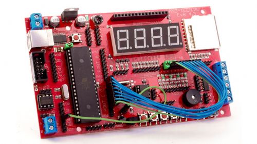
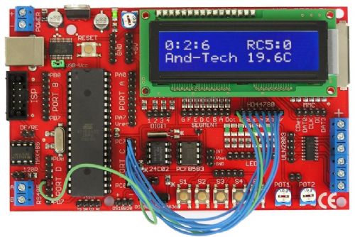
On the boards are soldered male connectors for maximum durability and the connections between the microcontroller and peripherals are made with female-to-female wires. Excellent configurability and great educational value (the beginner make the connections similar to using a breadboard, except that these "breadboards" have a lot of peripherals where only the power traces etched on board are connecting them together). Hope these will help you in making a great development board. A contest between members here will be a good idea? Hobbit name: Togo Toadfoot of Frogmorton Elvish name: Mablung Miriel Beyound Arduino Lang |
||||
| vasi Guru Joined: 23/03/2007 Location: RomaniaPosts: 1697 |
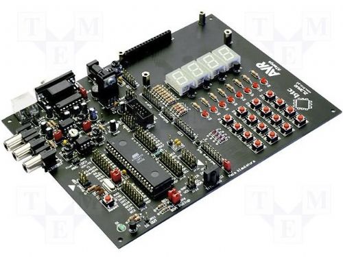
Here is another great homemade board 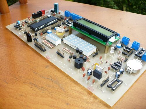
Link This one is for AVR, PIC and MSP microcontrollers, and this means that not even the power and oscillator pins are connected on the microcontroller... Hobbit name: Togo Toadfoot of Frogmorton Elvish name: Mablung Miriel Beyound Arduino Lang |
||||
| Zonker Guru Joined: 18/08/2012 Location: United StatesPosts: 772 |
WOW..!! Great idea Vasi.. I didn't think of this side of things yet, but your thinking here is BANG ON..!! If we are going to be spinning up some new PCB designs, then this issue needs to be addressed.. And yes, PCB's AND PDF learning manuals too... I too have "seen the look" in a kids eyes, when, for the first time... HE GETS IT..!! (kinda like flying solo in your UL for the first time) The smile comes out, the pride gets a notch up, the bucket is almost empty, an they want MORE..! This is actually awesome, cause, now, they are self driven ... (sweet) We will be speaking more about this... Thanks Vasi.. 
|
||||
| bigmik Guru Joined: 20/06/2011 Location: AustraliaPosts: 2981 |
Vasi, I love the idea of an `ALL in ONE' Prototype development board. And would entertain using one but its only practical for use as a learning and/or developing platform. It is not practical nor economical to use as a final stage PCB. I decided to design my PCB for, my purposes, to mount a uMite in a final working environment.. It IS minimalist by design and I intend to power it of a readilly available USB plugpack power source. I tossed around fitting a mini-USB header for power, and a power management chip but decided I didnt need them and it added cost and complexity that I didnt need. I know My PCB isnt for everybody. Basically it is, of course, `horses for courses' ie. which platform suits the bill best for your application/purpose. That aside. This is what I feel is the final version of my PCB.. Sorry for the constant flooding of this thread... I have implemented Lou's suggestion for a LP MCP1702 reg and BobD's suggestion of switchable 5V/3v3 for the I2C as I could fit them with minimal fuss. SCHEMATIC 2014-04-15_013247_mmite.pdf ARTWORK 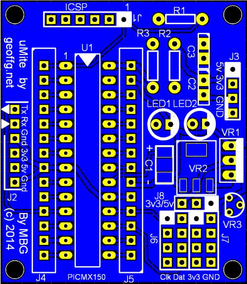
Regards, Mick Mick's uMite Stuff can be found >>> HERE (Kindly hosted by Dontronics) <<< |
||||
| vasi Guru Joined: 23/03/2007 Location: RomaniaPosts: 1697 |
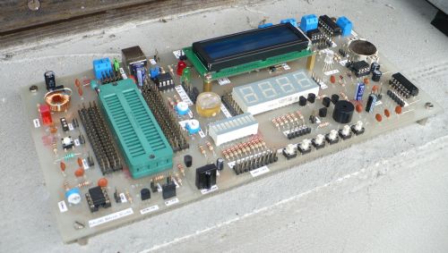
Zonker, I have one of those boards and I know how useful are. My board is for 40pin ATmegas but when I develop for PICs, I remove the micro (in fact I did a separate board for ATmega, to keep it away from the dev.board ) and connect the external PIC board to it via female-to-female wires (see the big image here).
And this video clip is one of the applications (I have it written in JALv2 and PMP). You know? It masks the electronics at first. You say to the kid: [quote="PinkFloyd"] - Teacher! Let the kids alo... pardon, I meant to say: - See? You connect this microcontroller pin, to this LED pin and the code is this. See how it blinks?[/quote] It allows the kid to concentrate on the code and seeing the result, is fantastic. And making blinking combinations for awhile, he advances to the next peripheral. And later, when acquired enough programming knowledge, he can step into the basic peripheral interfacing (hardware). Hobbit name: Togo Toadfoot of Frogmorton Elvish name: Mablung Miriel Beyound Arduino Lang |
||||
| MicroBlocks Guru Joined: 12/05/2012 Location: ThailandPosts: 2209 |
The all in ones are exactly the boards i dislike the most. Ones you have something working you need to transfer it to a pcb. That process is especially for non experts difficult. It is open to mistakes while transferring your working prototype to a schematic and then you need to design a pcb. Lots of extra skills needed to do that. If you have a project that needs only 20% what is on board then that board is 80% wste. With small modules those problems are prevented. Ones you develop something with small modules, the end product can be the same. You never use more then necessary, saving money. If you need two or more mcus (like with IR, RF, etc) you only spend money on the modules you need. Having two or three 'all in ones' can get pretty expensive. Often those boards have for example the MCU you need, but not exactly the right LCD , temperature sensor, or RTC or other part, rendering the board even more useless as you are more or less forced (if you want to keep the project within budget and physical dimensions) to use the parts that were chosen. Over time parts can get obsolete or much cheaper alternatives parts become available. Kids especially are good at releasing some blue smoke. :) If a part on that development board went up in smoke, good luck changing it. How to solve it, having spare development boards? With small modules you just replace that specific module. I have used several of the Mikro electronics boards and while they have lots of stuff on them even they have chosen to use modules to extend the capabilities as very often what you want is not on the main development board. The Arduino form factor has been proven to be highly successful, more than any other development platform. Not only because of the software and libraries but also the use of a defined connector. The only part i don't like is the often huge size of the 'shields' and that they only can be stacked which in my opinion is a major disadvantage. Also you often end up with a monstrous looking end product which forces you to do a complete schematic and pcb design. The huge difference in parts used for development, prototype and final product should be much easier. With small modules you can get very close to using the same parts for those steps, lowering costs and decrease development time substantially. Microblocks. Build with logic. |
||||
TassyJim Guru Joined: 07/08/2011 Location: AustraliaPosts: 6538 |
Mick, I like your PCB. I did purchase AUTOTRAX DEX but have been sidetracked lately and haven't had time to play. One thing I did notice (and I see it in your schematic)- the pin numbering on the CPU is 'strange'. I am used to the numbering going anticlockwise all the way around just like the actual pinouts. DEX seem to like top to bottom for the left hand side and then top to bottom again for the right hand side. I would have the order for the right hand side (pins 15 to 28) reversed. I did start making my own parts but that's when I got sidetracked.... I think I will be using veroboard for a while yet. Jim VK7JH MMedit |
||||
| vasi Guru Joined: 23/03/2007 Location: RomaniaPosts: 1697 |
You are describing the DIY process. Nothing wrong on this site or on the Maker community. The all-in-one boards were designed specially for the educational environment. Are compact and cheaper than a kit/box full of separate Arduino shields who are hard to put together in an arbitrary configuration. A box which can lose its content in a student class and require a lot of space, including a breadboard for the assembly. The all-in-one boards helps you with the basics first in the software area and especially good for people who are yet to learn the basics in peripheral interfacing without the need to spend a little fortune for every new chapter they learn. You don't need to make separate boards for every 20% project and not required to make final/commercial boards when you just started to explore this wonderful world. Is the best answer to the Arduino industry (not from the Manufacturer point of view - is not the case). Then, when the need arise for project boards, you are eager to learn and the all-in-one boards continue to be useful in developing the libraries you are packing with your Arduino like commercial boards. But then, you are no longer a beginner but a one of the many producers of Arduino boards and solutions who look to sell their boards as best as possible. Hopefully, you will not forget that once you was a poor student who did a DIY all-in-one board
P.S. For many DIY-ers, transforming a schematic to a PCB is the most entertaining video game possible, no matter the level of knowledge. Hobbit name: Togo Toadfoot of Frogmorton Elvish name: Mablung Miriel Beyound Arduino Lang |
||||
| WhiteWizzard Guru Joined: 05/04/2013 Location: United KingdomPosts: 2991 |
Mick, (sorry Zonker for using your thread but it is related to 28pin MicroMite!) Nice useful board. Looked at schematic and have three minor track-layout modifications to suggest (take them or leave them!) 1> Allow the option to add 100nF decoupling caps on each power input to the PIC (allowing for 0.1" pitch caps wont take much board space) 2> Place a 100ohm resistor in series to Pin1 on ICSP to add protection for the PIC and PicKit3 (avoids potential risk of bricking PIC if you were to accidentally press the button on the front of the PicKit3) 3> Include two solder jumpers (or 0.1" header jumpers if you can squeeze them in) for independently disabling the LEDs These inclusions would make the board a tiny bit more practical (and for near zero cost), while still remaining fit for your intended purpose. Regards, Phil |
||||
| bigmik Guru Joined: 20/06/2011 Location: AustraliaPosts: 2981 |
Gday WW, All, I have submitted the artwork for quotation, It may be possible to do an update as I havent yet accepted the quote,(it has just come in my new emails and I need to peruse it fully, but I am generally happy with the quote, probably a bit more than iTead but I have dealt with them before and its comparable) Yes! I thought of them whilst I was checking but it slipped my mind. there are only the 2 x 0.01uf Caps associated with the VReg.. A wise mod that costs nothing... A reasonable idea, I have never actually blown one and, personally, I have never actually held the pickit whilst programming, so it is a bit low on my list, it certainly could fit easilly enough.. If I re-do I will add it. That area is VERY tight and may not be do-able, I figured as it is designed for final application you would either add them or leave them off.. It probably wont get done or at best maybe a couple of solder pads default linked for LEDs on. I dont really like that idea myself so it may not get into my new versio... I need to think on it. Comments anyone? Yes, agreed.. but as I have started the process it may not be possible to change at this time. Thanks for your, quite valid and reasonable, constructive critism.. Rest assured I have taken it on board. Regards, Mick Mick's uMite Stuff can be found >>> HERE (Kindly hosted by Dontronics) <<< |
||||
| bigmik Guru Joined: 20/06/2011 Location: AustraliaPosts: 2981 |
Hi Jim, Yes that is something I noticed (all too late) myself.. The schematic is numbered ass about but then, it is NOT a representation of the actual pin out of the chip anyway so I left it as is. The PCB artwork numbering IS correct.. It is not difficult to change the pin layout on the schematic part but I decided to leave it.. I am still getting used to AUTOTRAX myself and there are a few things I need to get my head around. The thing I dont really like is the internal router it is just Verticals one side and horizontals the other.. but it is very easy and intuitive to use that as a base and put the tracks where you want... The inital route had about 100 vias... I got it down to none. Regards, Mick Mick's uMite Stuff can be found >>> HERE (Kindly hosted by Dontronics) <<< |
||||
| WhiteWizzard Guru Joined: 05/04/2013 Location: United KingdomPosts: 2991 |
Mick, Regarding the LEDs - I agree you could simply leave them out if not required. Another idea that I have used in the past is to simply buy some stackable headers, and chop them down into 2-way sockets and solder this in the LEDs board position. This then gives the option to plug in an LED (to visually test power ok, and then remove LED once circuit working ok (to reduce current consumption). You can purchase a batch of Arduino stackables so cheaply online and use these for the above purpose. When you cut them down DONT try and cut between pins (ie dont try and make a 6-way into thee 2-ways). Instead cut on a pin (and lose it) so a 6-way would become a 3-way and a 2-way. Confused yet??? 
Also regarding the recommended resistor on Pin1 ICSP, you can mount this vertically to save footprint BUT not too close to ICSP otherwise it could get in the way of the PicKit itself. WW |
||||
| The Back Shed's forum code is written, and hosted, in Australia. | © JAQ Software 2026 |
