
|
|
Forum Index : Microcontroller and PC projects : Armmite F4: programming the firmware
| Author | Message | ||||
| Volhout Guru Joined: 05/03/2018 Location: NetherlandsPosts: 5879 |
Dear matherp, When I was porting my MX170 code to the F4 platform I noticed that the MMbasic interpreter uses pin numbers (chip pin numbers). The silkscreen on the board however shows port reference (i.e. PB12, PC0). The only clear reference between the 2 I found in a circuit diagram of the board. Since the silkscreen shows port numbers, can this also be implemented in the interpreter ? Strange enough, in the OPTION TOUCH PB12,PC5 you use port numbers, and not pin numbers. But this does not work in a basic program (at least not for the numbers I planned to use). Regards, Volhout. P.S. if (for compatibility reasons) it needs to be an integer, could we use the integer in hexadecimal form: E1 for port PE1, E12 for port PE12, B7 for PB7, the highest port number is E anyway on this chip. Not sure about the H7...?? Edited 2019-10-03 05:09 by Volhout PicomiteVGA PETSCII ROBOTS |
||||
| matherp Guru Joined: 11/12/2012 Location: United KingdomPosts: 11332 |
This works for all pins that are available to the user. Many pins are allocated permanently to the display. See page one of the thread for pins that are available. Any in the list that show { NULL, 0, PUNUSED , NULL, 0}, are not usable from Basic |
||||
| ceptimus Senior Member Joined: 05/07/2019 Location: United KingdomPosts: 130 |
The SD card did work on the larger board so I tried hooking up the display copying the connections I'd used for the smaller (correct) board. The display flickers when GUI TEST LCDPANEL is executed but doesn't show any circles. Looking at the schematics for the two boards the connections to the TFT connector are almost the same, the only differences being that on the (correct) small board: 21 FSMC_A18 22 FSMC_NE1 on the larger board 21 is connected to FSMC_A6 and 22 to FSMC_NE4 I went looking for where the two correct signals are routed on the larger board - FSMC_A18 goes to the (not fitted) static ram chip on the back (pin 28) but I couldn't find FSMC_NE1 on the schematic at all. So I'm giving up for now. I contacted Banggood by email and informed them of their mistake but I've not heard anything back yet - I think there may be some holiday going on in China at the moment. |
||||
| Volhout Guru Joined: 05/03/2018 Location: NetherlandsPosts: 5879 |
Dear matherp, I am still investigating why my STM32F407VET6 board will not run your ARMmiteF4 basic software. That is...Only the first version you made specifically for the serial port runs, and runs reliable. But even the second version you made for serial port, does not work on my board. That image is larger. I noticed following measuring voltages on the board: - When the chip starts up in DFU download mode (BOOT0=1) all the JTAG pins on the F407 are either high impedance, or active driven. When running ARMmiteF4 code, the input pins have an weak pulldown enabled (with 10k pullup resistor, on my board the Vhigh=2.5V). If that relates to the problem, I don't know, since I measure this with the one and only working ARMmiteF4 code for my board. I measure this at : PA6, PA7, PB3, PB4, PA13, PA15. Especially the JTAG pins should default to weak pullup, not pulldown, but better high impedance, since there are HW pullups and pulldowns (like in DFU mode) I am very interested in the option bytes (they set sector protection on the flash). Do you reprogram these with the CUBE software ? If not, is there any way I can inspect them and see if they are causing my problem. Maybe you know what these bytes should be. Additionally there was a post on the ST forum that on their USB stack there would be provision of a GPIO pin that indicates when the CPU is ready for USB. That pin would be used to connect to the 1.5k resistor (in stead of a fixed pullup of 1.5k). They did that to avoid critical timing (the host will try to enumerate the device within 100mSec after the high is detected). Can you find in your code if such pin exists, and what pin it is. I hope you don't get tired of me. I am intrigued by the problem. Volhout PicomiteVGA PETSCII ROBOTS |
||||
| matherp Guru Joined: 11/12/2012 Location: United KingdomPosts: 11332 |
To program option bytes use the OB tab on Cubeprogrammer. Mine as follows: 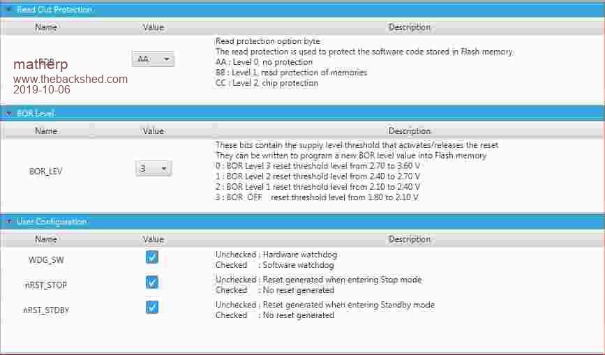 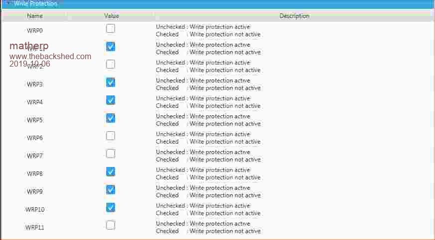 NB: WP values seem to be different each time I read them but in essence there should be no WP Edited 2019-10-06 03:50 by matherp |
||||
| Volhout Guru Joined: 05/03/2018 Location: NetherlandsPosts: 5879 |
My chip must be defect. Each time i read the write protection flags, the bits are different. Either through usb or through serial. This was the last try. In the bin with the F4. But I am becomming more and more charmed bij MMbasic, so I ordered a pi zero. No ADC, but fast.... only wonder how fast it boots with raspbian buster lite. And if you can run it headless after configuration is done. New challenges. Grogster made a board for the pi zero. Ill look into that one. Thanks all for your help. But it seems all energy in the world cannot save this chineese F4 monster. Edited 2019-10-06 19:07 by Volhout PicomiteVGA PETSCII ROBOTS |
||||
| lizby Guru Joined: 17/05/2016 Location: United StatesPosts: 3753 |
No problem, so far as I know, with continuing to use stretch light for the rpi-zw with MMBasic. I'd be interested to know if Buster gives you anything additional on the zw. You can set it up headless from the beginning, with no need ever to hook up monitor and keyboard: headless rpi-zw Sorry you got a dud. I have 7 F4s working. Edited 2019-10-06 22:23 by lizby PicoMite, Armmite F4, SensorKits, MMBasic Hardware, Games, etc. on FOTS |
||||
| matherp Guru Joined: 11/12/2012 Location: United KingdomPosts: 11332 |
Minor update to better support WS2812 LEDs ArmmiteF4.zip New syntax is WS2812 type, pin, array%() type is O - original WS2812, B is WS2812B, S is SK6812 The code changes the timings of the pulses to suit the different variants Test code. Works on any string up to 64 LEDs, just change the type to suit your version or use trial and error Dim b%(63) Do For i=0 To 63 b%(i)=RGB(20,0,0) Next i Timer =0:WS2812 B,3,b%():Print Timer:Pause 500 For i=0 To 63 b%(i)=RGB(0,20,0) Next i WS2812 B,3,b%():Pause 500 For i=0 To 63 b%(i)=RGB(0,0,20) Next i WS2812 B,3,b%():Pause 500 For i=0 To 63 b%(i)=RGB(20,20,0) Next i WS2812 B,3,b%():Pause 500 For i=0 To 63 b%(i)=RGB(20,0,20) Next i WS2812 B,3,b%():Pause 500 For i=0 To 63 b%(i)=RGB(0,20,20) Next i WS2812 B,3,b%():Pause 500 For i=0 To 63 b%(i)=RGB(20,20,20) Next i WS2812 B,3,b%():Pause 500 For i=0 To 63 b%(i)=RGB(0,0,0) Next i WS2812 B,3,b%():Pause 500 Loop |
||||
| RonnS Senior Member Joined: 16/07/2015 Location: GermanyPosts: 122 |
many thanks to MatherP for this graet work !  i have a little problem : since some time my board loses the calibration settings for the touch display, after power down and power up i have to calibrate the TFT, autorun does not work any more. in the listing options, only the TFT- settings and touch displayed nothing else i had "reflash d" the chip with "full erase" but it had no effect somebody has an idea to fix it ? or what can be the reason ? thanks Ron |
||||
| matherp Guru Joined: 11/12/2012 Location: United KingdomPosts: 11332 |
Ron, looks like I've introduced a bug - now I need to understand when and how since I'm not aware I've changed the relevant code �  Please try the attached: ArmmiteF4.zip Edited 2019-10-30 00:15 by matherp |
||||
| RonnS Senior Member Joined: 16/07/2015 Location: GermanyPosts: 122 |
thanks MatherP for fast response, this zip contents only a *bin file should it not be a *hex..? The problems occurred about 1 week ago . first I thought the display would be defective |
||||
| matherp Guru Joined: 11/12/2012 Location: United KingdomPosts: 11332 |
bin, hex and elf are interchangeable. Cube programmer is totally happy with bin |
||||
| RonnS Senior Member Joined: 16/07/2015 Location: GermanyPosts: 122 |
Peter, that was not successful, maybe there is something wrong with my board? nobody else with the same problems ? |
||||
| matherp Guru Joined: 11/12/2012 Location: United KingdomPosts: 11332 |
I've just downloaded the posted version and programmed a board and OPTIONs are definitely working. There was a hard fault which I have fixed so make sure you are really programming the new version. Cube programmer is very good at remembering the last location and keeps it when you move to the programming tab confusing everything!!! So once in the programming tab browse to the new version and re-program. |
||||
| RonnS Senior Member Joined: 16/07/2015 Location: GermanyPosts: 122 |
.. sorry Peter it doesnt work. 100% sure i use the right file.. after power down and power up it lose the calibration, doesnt start at autorun and.. the "magic" reconnection does not work anymore..all other things are alright 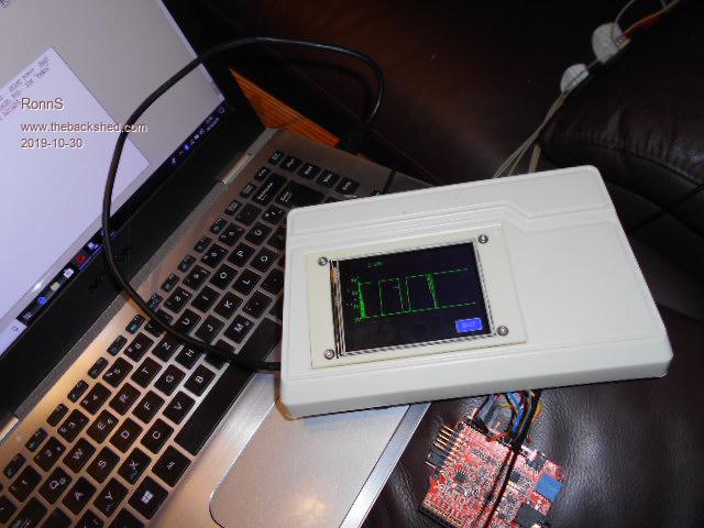 |
||||
| ceptimus Senior Member Joined: 05/07/2019 Location: United KingdomPosts: 130 |
It works for me (using the 3.2 inch ILI9341 16-bit-bus display). If you just update the firmware, then without uploading your program do a GUI CALIBRATE, cycle power, then GUI TEST TOUCH, what happens? Maybe the fault you're experiencing only happens when a large program is present? |
||||
| Plasmamac Guru Joined: 31/01/2019 Location: GermanyPosts: 617 |
led works like a charm . Thx matherp btw : is it possible to get the mod play routine on this board ? many thanks J�rgen Plasma |
||||
| RonnS Senior Member Joined: 16/07/2015 Location: GermanyPosts: 122 |
@septimus.. all done so..... the calibration ist out of range again... i purchased an new board :) thx |
||||
| Plasmamac Guru Joined: 31/01/2019 Location: GermanyPosts: 617 |
Hi, Can anyone here shows me an example of a working ADC Routine ? My test code is from matherp (f7) code. Bridge here PC0 and PA2 The DAC routine works (i can hear pulse) The ADC isnt working if it is connected to the DAC ( no results). If i disconnect the Dac pin and put my hand on the ADC pin i get results. even the ADC 'interrupt' isnt working. Am i wrong here ? initProg readv End ' Sub InitProg NumSamples = 32 Freq = 50 * NumSamples Print "Frequency is ",freq,"Hz" Dim Volt_Raw!(NumSamples - 1) ' 'create a sine wave with 4 times the frequency of the ADC sampling frequency 'this ensures the value will move between samples under all circumstances ' Dim d%(NumSamples*4-1) For i=0 To (Numsamples*4-1) d%(i)=2048+1800*Sin(Rad(i*360/(Numsamples*4))) Next i DAC start freq*4,d%(),d%() End Sub ' Sub ReadV Local i ADC OPEN Freq,15 ADC trigger 1,0.3 ADC START Volt_Raw!() Print "Idx";Tab(8);"Volts(Idx)";Tab(24);"Delta" For i = 1 To (NumSamples - 1) Print i;Tab(8);Str$(Volt_Raw!(i-1));Tab(24);Str$(Volt_Raw!(i)-Volt_Raw!(i-1)) Next i Print i;Tab(8);Str$(Volt_Raw!(i-1)) ADC CLOSE End Sub Plasma |
||||
TassyJim Guru Joined: 07/08/2011 Location: AustraliaPosts: 6528 |
Where did PA2 come from? For the F4: Using PA4 as the source: Jim VK7JH MMedit |
||||
| The Back Shed's forum code is written, and hosted, in Australia. | © JAQ Software 2026 |
