
|
|
Forum Index : Microcontroller and PC projects : Proto Board for the uMite 28
| Author | Message | ||||
bigmik Guru Joined: 20/06/2011 Location: AustraliaPosts: 2981 |
Lads, OK This is the final FINAL version.. I have added the 2 bypass caps that WW suggested as well as a 100R resistor to protect accidental `bricking' of the PIC. I am presenting this version for Manufacture now. Regards, Mick SCHEMATIC 2014-04-15_112013_mmite.pdf OVERLAY 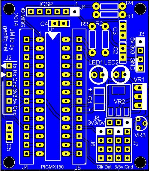
Mick's uMite Stuff can be found >>> HERE (Kindly hosted by Dontronics) <<< |
||||
| viscomjim Guru Joined: 08/01/2014 Location: United StatesPosts: 925 |
Hi BigMik, Keep us posted on availability of this one. I like it. Can be very useful for several projects!!! |
||||
| bigmik Guru Joined: 20/06/2011 Location: AustraliaPosts: 2981 |
Hi Viscomjim, I have submitted it for manufacture by my PCB FAB house (sitopway.com) on 1.6mm (I thought of 1.2mm but decided on standard thickness) lead free HASL material. I should be able to provide them for $3.00Aus each plus $1 postage in Australia and $3 International. This allows for PAYPAL Commission and leaves a small bit towards a beer. I reserve the right to change these when they arrive but it is a good ball park figure. Regards, Mick Mick's uMite Stuff can be found >>> HERE (Kindly hosted by Dontronics) <<< |
||||
| viscomjim Guru Joined: 08/01/2014 Location: United StatesPosts: 925 |
bigmik, do you plan on offering a fully populated version or just the board. Either way, I am interested. Did they give you any indication on the timeframe for your boards? Thanks Jim |
||||
| bigmik Guru Joined: 20/06/2011 Location: AustraliaPosts: 2981 |
Hi viscomjim, That is probably getting a little bit ahead of things at this stage... Whilst I certainly could build one up and sell a complete unit I dont want to start any major construction (as profitable as that may be). I need to build one up and test it first to make sure it is functional. As I have mentioned I designed this board to suit my purposes and I am very pleasantly surprised that it has been received so positively by others... I am torn between marketing it in a big way and maybe making some profit, but I also look at this board compared to others I have designed, and compared to WW and Zonkers "fully optioned" offerings, and it is not all that great. I feel it could be improved by adding a mini USB header, not for USB connectivity, but for power input but I opted, due to lack of PCB space and the fact these connectors are not the easiest to solder, to leave it off.. I still wonder if that was the correct decision or not.. Anyway that is what I have done and unless I redo it that is what we get. All that ranting aside, if you think you wont be able to solder it up, I could build you one, I reckon no more than 30-40 minutes work, but dont expect soldering like WW's. Now I have a question for the group.. Headers J4 and J5... Should these be female or male? Or user decide? I gererally subscribe to male pins on PCBs as they wont wear out like female sockets can, but female would allow an LED or resistor to be poked in easilly.. Hmm, conundrums... Regards, Mick Mick's uMite Stuff can be found >>> HERE (Kindly hosted by Dontronics) <<< |
||||
| WhiteWizzard Guru Joined: 05/04/2013 Location: United KingdomPosts: 2991 |
Mick, Remembering this PCB was originally for your own use then assuming 'compactness' is not an issue I would consider doing the following. Use short pin female headers soldered onto the board. Then place enough 2-way male headers into these female to make each pin effectively a male header (yes they will be a bit tall - but thats why I mentioned above if 'compactness' was not an issue). Now you have the flexibility - male where you want to, or female if you remove the relevant 2-way male header pins. I would avoid the use of single pin males as these would 'spin'. If however you need a single female (Im still talking about the headers!  ) then use multiple male headers either side ensuring you don't have any single males. Hopefully you followed this! (A picture paints a 1000 words . . . . . ) ) then use multiple male headers either side ensuring you don't have any single males. Hopefully you followed this! (A picture paints a 1000 words . . . . . )
OR (as something I have used very successfully for my own use in the past) is: Why not use Long Pin Female stackable headers mounted on the underside of the PCB. Then you can use the long pins (which are sticking out the top) like normal male headers, and have the option underneath to have females for temporary plugging in 'things'. This method allows you to then mount the PCB upside down into a breadboard to give more working holes. Sorry Mick, just added MORE conundrums for you 
|
||||
| bigmik Guru Joined: 20/06/2011 Location: AustraliaPosts: 2981 |
Hi WW,All, I understand what you say about single males and females (they are unstable and twist about too much) 
What you say about the long female stackables could be done but the ones I have seen dont have square male pins and are actually flat `rectangular' shaped and dont reliably plug into female header sockets so I wouldnt use them.. These are like Arduino risers... I am not a fan of mounting the females under the PCB unless it was going to plug into another PCB.. and Compactness is generally what I look for. I am tending towards ALL Males on the PCB as the Female-Female link wires are readilly available and cheap. I was trying to get an opinion from what others would think about this. On thinking along this, it is of course entirely up to the end user and what environment it is going to be used for.. The fact that the J4 and J5 headers have ALL (except pin 20 Cap C1 +ve connection) it lends itself to a daughter board for USB/TTL relays, LEDs etc. But of course it could also have the pins/sockets facing down on the underside of the PCB to plug this PCB into larger PCBs and thus become a CPU module.. I dont see myself doing either but I am thinking of the possibility of a Training board such as Vasi displayed earlier for learning about basic and various hardware concepts.. If that was designed what would we wish to offer? LCD? If so I2C or Parallel interface? Various LEDs? 7Seg Modules? Switch matrix? Stepper motor driver? Buzzers? On board Logic probe? But what market would you have? Is there a demand for such a beast for uMite? Should it be for a MaxiMite? More Mick Ramblings.... Regards, Mick Mick's uMite Stuff can be found >>> HERE (Kindly hosted by Dontronics) <<< |
||||
| MOBI Guru Joined: 02/12/2012 Location: AustraliaPosts: 819 |
@Mick, Here I go again wrt I2C. I think it is underutilised and as we are dealing with a controller here, we don't really need lightning speed. Is it possible to dedicate the uMite I2C pins to a header so that an external bus (say 5 pin) could be connected to take care of functions listed above. I would also mount the pull up resistors on the external bus as "plug in" to cater for differing I2C speeds. Just about every stand alone controller would need date/time and the RTC is already I2C so it is not such a big deal provide a bus connector to allow other functions. The dedicated uMite keypad and LCD are great but don't leave a lot of pins for the outside world. If I were to pick one to fit to the test board, I'd pick keypad as it is "instantaneous" and transparent. The LCD is just as easy to drive in I2C form as the uMite version, also it is just as easy to swap to a 7seg if you want visibility and numbers only. I have a few I2C designs in my stable that are easily vero-boardable and with source/hex code plus PCB layout if there is any interest in that direction. David M. |
||||
| MicroBlocks Guru Joined: 12/05/2012 Location: ThailandPosts: 2209 |
I am working on pcb that has all 'bus' signals on a header on one side of the print. It would then allow for modules to be made that use one or more of the 'bus' signals. Any specific mcu pins that are not on that bus will be on a separate header. This will allow bus modules with different mcu modules. I have a whole bus system figured out that allows for plugable modules and has 2xI2C, 2xspi, 2x serial, 4 gpio, 3.3v and 5v, gnd and reset. Depending on the mcu used one or more of these bus signals are used to communicate with other modules. I have posted about this before but now that the micromite is final i can finish my design and showed it soon for feedback. Microblocks. Build with logic. |
||||
| Zonker Guru Joined: 18/08/2012 Location: United StatesPosts: 772 |
Happy Easter Everyone..!! Just wanted to post a quick update of the uMite Prototype Board, "Rev-B" that fixes the registration issue with the DFN part. (and the silly spelling on back)
2014-04-20_210350_uMite-28_Prototype_Board_Rev_B.zip Take a look and see if there are any errors in there.. If not, then this one's a done deal..!! Next...
Thanks Gang..! EDIT: Yep, another update... I was thinking, since orders for the board have settled down here at the shed, I think it would be a good idea to pack up the last 6 "full builds" with the 20 flats and send them over to Phil to slot up on the website... It will be a bit to get some "fresh" stock created and this could serve as a slight buffer for the shelf... Took a peek at the gerbers... 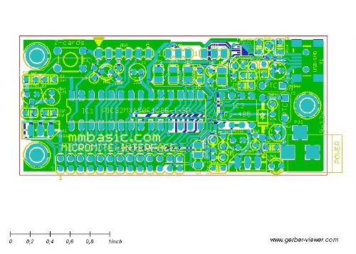
They seem to be in order... |
||||
| ajkw Senior Member Joined: 29/06/2011 Location: AustraliaPosts: 290 |
Hi Zonker, Do you still have one of the six available? If so I think I will get one. Cheers, Anthony. |
||||
| psergiu Regular Member Joined: 09/02/2013 Location: United StatesPosts: 83 |
Please consider using UEXT. There are already a bunch of modules using this connector. See https://xkcd.com/927/ |
||||
| MicroBlocks Guru Joined: 12/05/2012 Location: ThailandPosts: 2209 |
I considered UEXT, but it is not really suited for a small! microcontroller board. Consider this to be the new standard. 
Just kidding. There is lots of value in already accomplished standards and using those is certainly a goal of what i have in mind. I just made sure i have all of the signals available on one side of the board so that connected it to other modules from the same series is very easy, while still allowing to have carrier (backplane) boards that can adapt to other standards. I have planned a carrier board that has 6 UEXT connectors. Also one that uses the Mikro bus, one that uses the Gadgeteer range and one that uses the Maximite connector. I have not decided which one(s) will be made final. My personal preferences are the UEXT and Maximite. Then there is also the GROVE system. Easy for analog sensors, single digital i/o and servos. I am preparing a post with all the details, expect it soon. Microblocks. Build with logic. |
||||
| bigmik Guru Joined: 20/06/2011 Location: AustraliaPosts: 2981 |
Hi Zonker, What silly spelling? I have looked at mine for about 10minutes and cannot see any spelling problem.... See I told you my eyes are bad. Mick Mick's uMite Stuff can be found >>> HERE (Kindly hosted by Dontronics) <<< |
||||
jman Guru Joined: 12/06/2011 Location: New ZealandPosts: 711 |
Dounload should be Download Jman |
||||
| vasi Guru Joined: 23/03/2007 Location: RomaniaPosts: 1697 |
Hmmm, that makes him a Romanian... Hobbit name: Togo Toadfoot of Frogmorton Elvish name: Mablung Miriel Beyound Arduino Lang |
||||
| bigmik Guru Joined: 20/06/2011 Location: AustraliaPosts: 2981 |
I could do worse than having you as a neighbor Vasi. 
Mick's uMite Stuff can be found >>> HERE (Kindly hosted by Dontronics) <<< |
||||
| JohnS Guru Joined: 18/11/2011 Location: United KingdomPosts: 4334 |
Or a Scot :) John |
||||
| Zonker Guru Joined: 18/08/2012 Location: United StatesPosts: 772 |
Morning Gents... Just wanted to post a quick update to give everyone a word document describing the jumper setting used on the prototype board. WhiteWizzard needed the doc for his website and I wanted to see that everyone here has access to it also... 2014-04-23_135754_MicroMite_PCB_Jumpers.zip Thanks..! |
||||
BobD Guru Joined: 07/12/2011 Location: AustraliaPosts: 935 |
Here it is as a PDF. It may be easier for some people to use. 2014-04-23_150205_MicroMite_PCB.pdf |
||||
| The Back Shed's forum code is written, and hosted, in Australia. | © JAQ Software 2026 |
