
|
|
Forum Index : Microcontroller and PC projects : Keyboard for Micromite Plus
| Author | Message | ||||
| MicroBlocks Guru Joined: 12/05/2012 Location: ThailandPosts: 2209 |
Holy smokes. That is some strong tape. Will be good for other purposes.:) I opened up mine and i think i can glue some wood along the edges so that the bottom plate can be screwed onto that. At least it will have something to 'bite' into. Some short countersunk m3 screws will probably work. Actually glueing the keyboard to the aluminum is not that bad. If you can mount everything on the aluminum and then just use the cover on top, the it does not need much to hold it down. Maybe with some magnets. It will look 'interesting'. kind of industrial prototype electronics lab kind of thing. 
Unfortunately i can not lasercut aluminum otherwise i would make the top of aluminum too. Maybe cnc will work, but that will takes some time. Microblocks. Build with logic. |
||||
| robert.rozee Guru Joined: 31/12/2012 Location: New ZealandPosts: 2541 |
a few thoughts: 1. there is a product called "De-Solv-it" that you can get from bunnings. it will render almost any non-glue adhesive unsticky. if you could have prised up a corner of your keyboard a fraction and dribbled some in such that is soaked into the tape, the adhesive would have released after about 10 minutes. "De-Solv-it" contains D-Limonene, a chemical extracted from citrus fruit. Eucalyptus oil will similarly unsticky adhesive, but is not quite so effective. D-Limonene has many of the good properties of the fabled 'universal solvent', without the bad property of dissolving the bottle it is contained within (or human flesh). 2. what if you had drilled right through the original mounting posts to the front of the keyboard, countersunk from above, and placed small bolts that ran from the front into tapped holes in the aluminium plate? it may have looked a tad 'heath robinson', but would perhaps have worked. 3. M3 bolts through the aluminium plate from underneath, with a little oil on the threads as well as a light coating on the plate. matching M3 nuts fitted (perhaps nylock with the nylon removed) with NO oil on the nuts. locate bolts/nuts in places where there is no plastic in the way. add epoxy resin to the plastic where the nuts will sit, place plate+bolts+nuts assembly in place and secure with bulldog clips, then wait for the epoxy to harden. remove the bolts and the plate should lift away, the nuts glued in place securely, but the epoxy unable to stick to the oily bolts or plate. cheers, rob :-) |
||||
Grogster Admin Group Joined: 31/12/2012 Location: New ZealandPosts: 9985 |
Yep, know of an use De-Solvi-It on many other things. I did not use it this time, as I did not think to. Not sure it would get into the 3M mounting tape though, as it is a gel-based tape, and as such, waterproof, so the de-solv-it would not be able to soak in like it can on paper-backed adhesives. It's worth a try though - I will stick a couple of bits of aluminium plate togeather with the mounting tape, then spray de-solv-it on it to see if it can release this stuff too. Se-solv-it is BRILLIANT for removing "Bits of sticker" 
Smoke makes things work. When the smoke gets out, it stops! |
||||
| WhiteWizzard Guru Joined: 05/04/2013 Location: United KingdomPosts: 2991 |
G, Please can you reveal the exact spec of that tape if you don't mind! I have an immediate requirement for something that 'strong' 
If you have a link as to where you purchased it from then that would also prove useful (hopefully not a 'one-off' eBay purchase!!) Thanks G  |
||||
| Grogster Admin Group Joined: 31/12/2012 Location: New ZealandPosts: 9985 |
Hey there.
VHB mounting tape, by 3M. "Very High Bond" - I keep almost saying "Bondage" - must stop that.
Link It can be purchased from most hardware stores. Wee rolls are about $15, big rolls are about $35, but it is money well spent if you want a permanent mounting. Smoke makes things work. When the smoke gets out, it stops! |
||||
| Grogster Admin Group Joined: 31/12/2012 Location: New ZealandPosts: 9985 |
UPDATE. The new 1B layout. TOP: 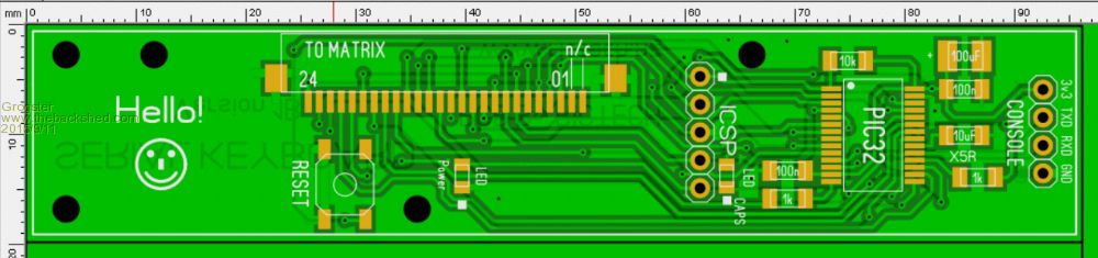
CHANGES: - Added a reset button, connected to MCLR. Pressing the "CONNECT" button now resets the PIC32 chip. - Removed the grounding link, and replaced with a grounding track for the ICSP. For the 1B board, I plan to use 8-core security wire for the link cable. Two cores for console TXD and RXD, one core each for MCLR, PGD, PGC, 3v3 and GND. The idea being that you can upgrade the firmware AND the MMBASIC code, all using the same cable. ...I am not sure how legal that is, with the ICSP side of things - adding a meter or so of cable to PGC and PGD might prevent the ICSP system from working correctly - I will run some tests with lengths of cable in front of the PicKit3 programmed and chip to see what happens. Smoke makes things work. When the smoke gets out, it stops! |
||||
| MicroBlocks Guru Joined: 12/05/2012 Location: ThailandPosts: 2209 |
I got a renewed interest in this pin and found in the datasheet that it is a input pin only. Furthermore and this is hidden in another datasheet this pin is fixed into the #MCLR mode leaving the factory. [quote=Microchip datasheet] If low-voltage programming is enabled (LVP = 1), the #MCLR Reset function is automatically enabled and cannot be disabled. The LVP bit can only be reprogrammed to '0' by using the High-Voltage Programming mode. The LVP bit in Configuration Word 2 enables single- supply (low-voltage) ICSP programming. The LVO bit defaults to a '1' (enabled) from the factory. MCLRE LVP #MCLR Pin 0 0 Disabled 1 0 Enabled x 1 Enabled The #MCLR pin is connected to Vdd through an internal weak pull-up [/quote] Hope this helps as it is not that obvious upon reading a single datasheet as this info is scattered. This is valid for the PIC16(L)F145x chips. Microblocks. Build with logic. |
||||
| Grogster Admin Group Joined: 31/12/2012 Location: New ZealandPosts: 9985 |
UPDATE: I have rebuilt the 2nd prototype of the little blue unit - this time, using the 2nd of two of the blue ones I had - all the others are black. 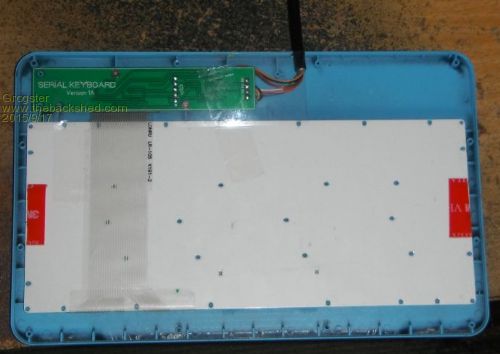
For this version, I wired up the ICSP to the connecting cable. I was unsure of just how legal that is with respect to the ICSP, but it seems to work just fine. The cable is quite short though - only about half a meter, as it is designed to complement an LCD unit that is right beside it, so no need to have a big long cable on it. The cable I used was an old 9-pin serial cable with the plugs cut off - that gave me nine cores and a drain wire plus foil. This arrangement allows for BOTH updating of the MMBASIC code via the console and XMODEM commands, or complete reflashing of the firmware via the ICSP, all on the one cable, without having to pull the KB to bits. You will note, however, that I have only used a tiny amount of VHB tape this time around, so that I don't actually have to destroy the KB to get it apart, if there is a next time. This one does not have the new PCB with the reset button in it yet. I am going to see if I can move the ICSP to the end with the normal console output, so that all wires can be soldered in the one place. However, this concept(ICSP over cable) is working OK. Smoke makes things work. When the smoke gets out, it stops! |
||||
| paceman Guru Joined: 07/10/2011 Location: AustraliaPosts: 1329 |
Hi Grogs, As I remember, those old nine wire serial cables were pretty stiff which would make connecting the little keyboard up to micro modules a bit of a pain - the old serial cables are getting a bit scarce these days too. A better option might be Multi-strand Ethernet cable (Cat 5, not 6) which is reasonably flexible and available everywhere. It's only got eight wires but the ground on the console connector and the ICSP connector are common so presumably only eight are needed. Not sure how the twisted pairs in the Ethernet cable might affect things but it would be worth a try. Greg |
||||
| Grogster Admin Group Joined: 31/12/2012 Location: New ZealandPosts: 9985 |
Not the cable I have - it is only 5mm OD, and all the cores are stranded, so it is pretty flexible. Perhaps just the cable I have access to? You could use anything within reason, I would think - even 8-core security wire, which was what I was going to use. The cable I used was a Dynamix branded one, and my local shop had them on the shelf. I don't think good old native 9-pin serial is quite dead yet.
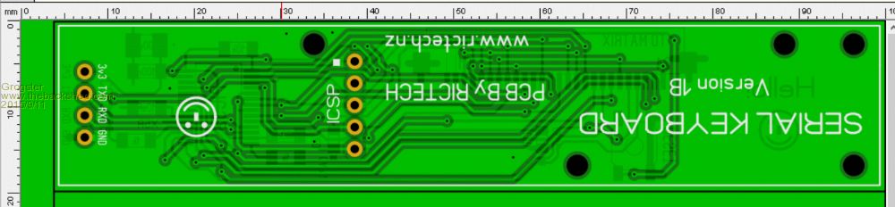
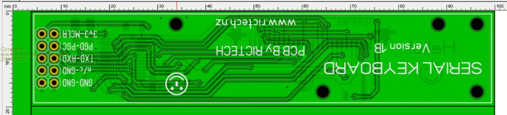
Here is the new PCB layout, with the console and ICSP all at one end of the PCB. Several other tracks were "Tided" in the layout, once the 5-way was gone. 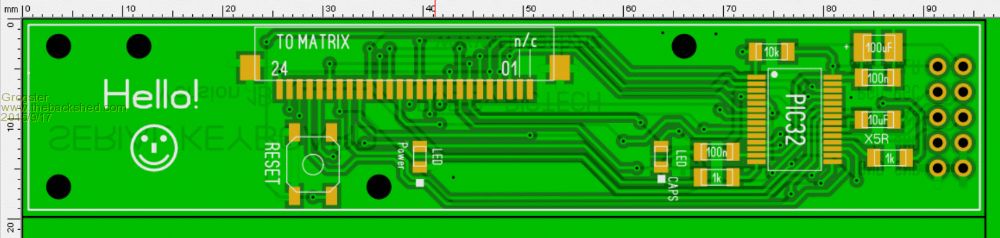
Smoke makes things work. When the smoke gets out, it stops! |
||||
| MicroBlocks Guru Joined: 12/05/2012 Location: ThailandPosts: 2209 |
Hi Grog, Received your package today! Right on time before the weekend. This will make working on the software much easier, until now it was just using my little breadboard with 8 buttons. :) I like your way of sending the parts, very clear where they have to go, and with tape they go nowhere. I was expecting one board, but thanks for sending a bunch of them. Now i have to buy a few more keyboards.  
I will glue some wooden pieces along the edge and try to use some screws. If i measured right i have about 5mm,that should be enough to hold it. Microblocks. Build with logic. |
||||
| Grogster Admin Group Joined: 31/12/2012 Location: New ZealandPosts: 9985 |
Glad they arrived OK. Yeah, I had plenty - more then I could use, really - of the PCB's, so I figured it would be good material to keep the envelope stiff. Glad you like the way I sent the parts - nice to know. Smoke makes things work. When the smoke gets out, it stops! |
||||
| MicroBlocks Guru Joined: 12/05/2012 Location: ThailandPosts: 2209 |
Ok, i have soldered it, put MMBasic on it and it works. Now i will continue with the software. Want those Function keys to work. :) Microblocks. Build with logic. |
||||
| Grogster Admin Group Joined: 31/12/2012 Location: New ZealandPosts: 9985 |
Have fun, and keep us posted! Smoke makes things work. When the smoke gets out, it stops! |
||||
| MicroBlocks Guru Joined: 12/05/2012 Location: ThailandPosts: 2209 |
I have some weird problem and need to do some troubleshooting. The chip resets when some of the 'row' pins are made an output. Sometimes it works for 5-10 seconds and then resets, sometimes it resets right away. The command i give from the prompt is Setpin 10,DOUT,OC (Or any other pins that are used for the rows.). On my DIP version of the same chip it works well, so it is not a software thing. Testing with only a multimeter does not get me deep enough. Have to check if the power dips when i do that, maybe a short. I already checked for shorts and continuity and that seems fine. Microblocks. Build with logic. |
||||
| paceman Guru Joined: 07/10/2011 Location: AustraliaPosts: 1329 |
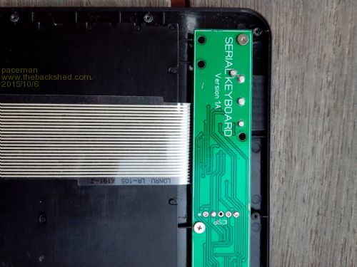
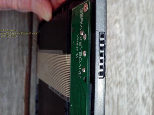
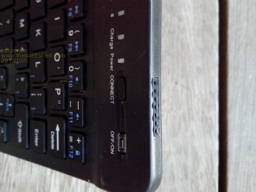
Hi Grogs, I've finally put mine together after waiting for the Chinese slowboat. Rather than run the ICSP lines out with the Rx/Tx/3.3v/Gnd cable I've modded the board (bit of a hack ) so that there is now a normal ICSP header available at the top edge of the keyboard. It fits pretty well and should be ideal for the occasional firmware re-flash.
I drilled the PCB and used a seven-pin right-angle header - see below. The two outer pins are not used but they and the middle pin (ICSP pin 3) are all soldered through to the opposite side Gnd fill to mount it tightly. Pins 1,2,4&5 were bent back out and connected with wirewrap cable to the ICSP connector. The Rx/Tx & power header now connects to nice flexible 4 conductor DuPont jumpers. I also put one of the very small momentary contact tactile switches on the board for a RESET (switches MCLR to Gnd). It pretty much exactly fits the ON/OFF switch position. Greg 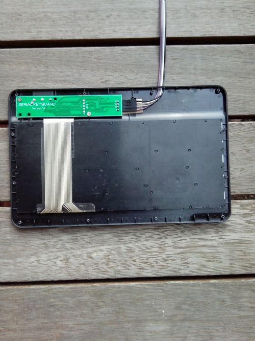

|
||||
| Grogster Admin Group Joined: 31/12/2012 Location: New ZealandPosts: 9985 |
That's a clever ICSP mod, Greg, well done. 
My 1B's are on the way from the factory. These are the ones with the "Reset" tact button added - the 'CONNECT' button. Did I ever get around to sending you(or posting here) the code I had for making it work? MicroBlocks(AKA TZA) wrote some pretty clever code, so that is probably what you are using. Smoke makes things work. When the smoke gets out, it stops! |
||||
| paceman Guru Joined: 07/10/2011 Location: AustraliaPosts: 1329 |
I don't know if you've updated your code but the only link I've seen on this thread is on page 10, i.e. the edited post on "27 August 2015 at 12:37am". I'm currently using that but there are a some bugs in it. I haven't tried any of Jean's (MicroBlock's) code yet, mainly because I'm not sure which version is "final" and what, if any, pin changes he's made for his code. BTW I'm using B24 firmware. Greg |
||||
| MicroBlocks Guru Joined: 12/05/2012 Location: ThailandPosts: 2209 |
The software on page 17 works but without the Fn and ctrl keys. It is still a work in progress but unfortunately i hit a problem as mine locks up. Development is because of that stuck. I have some chips on the way so i can continue with it once they arrive. If you use the code on page 17 of this thread make sure you add [code] 'Setup CapsLock and Power pins SETPIN Matrix.Indicators.CapsLock.Pin, DOUT SETPIN Matrix.Indicators.Power.Pin, DOUT [/code] Microblocks. Build with logic. |
||||
| paceman Guru Joined: 07/10/2011 Location: AustraliaPosts: 1329 |
Thanks Jean, I'll try that. |
||||
| The Back Shed's forum code is written, and hosted, in Australia. | © JAQ Software 2026 |
