
|
|
Forum Index : Microcontroller and PC projects : Stepper Project
| Author | Message | ||||
| PhenixRising Guru Joined: 07/11/2023 Location: United KingdomPosts: 1988 |
Stab in the dark here but it appears that those STEPPER GCODE commands are not strings. The manual shows them without the "". |
||||
| DaveJacko Senior Member Joined: 25/07/2019 Location: United KingdomPosts: 103 |
thanks, Phenix I removed the quotes, error now is "expected a string" removed the commas.. same replaced commas with spaces.. same thanks again, going to bed, cheers mate Try swapping 2 and 3 over |
||||
| phil99 Guru Joined: 11/02/2018 Location: AustraliaPosts: 3316 |
A minor item for the manuals. The original Stepper thread says Stepper is RP2350 only but neither Pico Revision 2 (10 May 2026) or Stepper manuals mention this. |
||||
Bryan1 Guru Joined: 22/02/2006 Location: AustraliaPosts: 2136 |
Morning Guy's well just got the X axis to wire up and ready to test  Now Lyle running the code does update the actual position nicely Now one I did find after the numbers are inputted for distance and feedrate when going to a different axis the previous data in the display box's is shown. Now Lyle running the code does update the actual position nicely Now one I did find after the numbers are inputted for distance and feedrate when going to a different axis the previous data in the display box's is shown.Also the display box's holding the X,Y,Z machine position does flicker and my shed radio is picking up the flicker. Nice touch putting the jog pins on page 5 mate as it does really neaten up the code. Will report in time after the setup all hooked up and for now I can just use my programmable power supply for the stepper power input. Regards Bryan |
||||
| mozzie Guru Joined: 15/06/2020 Location: AustraliaPosts: 400 |
G'day, DaveJacko, the MMBasic Stepper system only accepts a limited list of commands. As the developer (Peter Mather) commented earlier, this is not a full motion control system. It can however be the basis of one with a bit of effort on our behalf. If I have this correct the feedrate works with G1 so: STEPPER GC G1 F100 STEPPER GS "G1 F100" STEPPER GCODE G1,F,100 Also: A$="G1 F100" STEPPER GS A$ F_rate = 100 STEPPER GCODE G1,F,F_rate STEPPER GC G1 X10 Y10 Z10 A10 F100 The spindle controls is M3/M5 only, the S command is not implemented. A program for my coil winder parses the g-code file as it is read and only feeds supported commands to the MMBasic stepper system, this also allows tool changes and other functions to be implemented. Bryan, that is odd, the length / feed number-box's on my unit work as expected. The flicker is annoying, I have re-written the code so it only updates the display if something changes. SurGrind0003a.zip The 4" ST7796 displays arrived so I'll get one mounted this arvo and see how they look. Regards, Lyle. Edit: Oops, cut and paste error in code, now fixed. Edited 2026-05-20 14:10 by mozzie |
||||
| Bryan1 Guru Joined: 22/02/2006 Location: AustraliaPosts: 2136 |
yes mate that code was buggy and the lcd did a white out, now with that code from yesterday got the X axis trying to move so playing with current and step resolution. I did take some time to get it all wired up and here is a picture of the setup 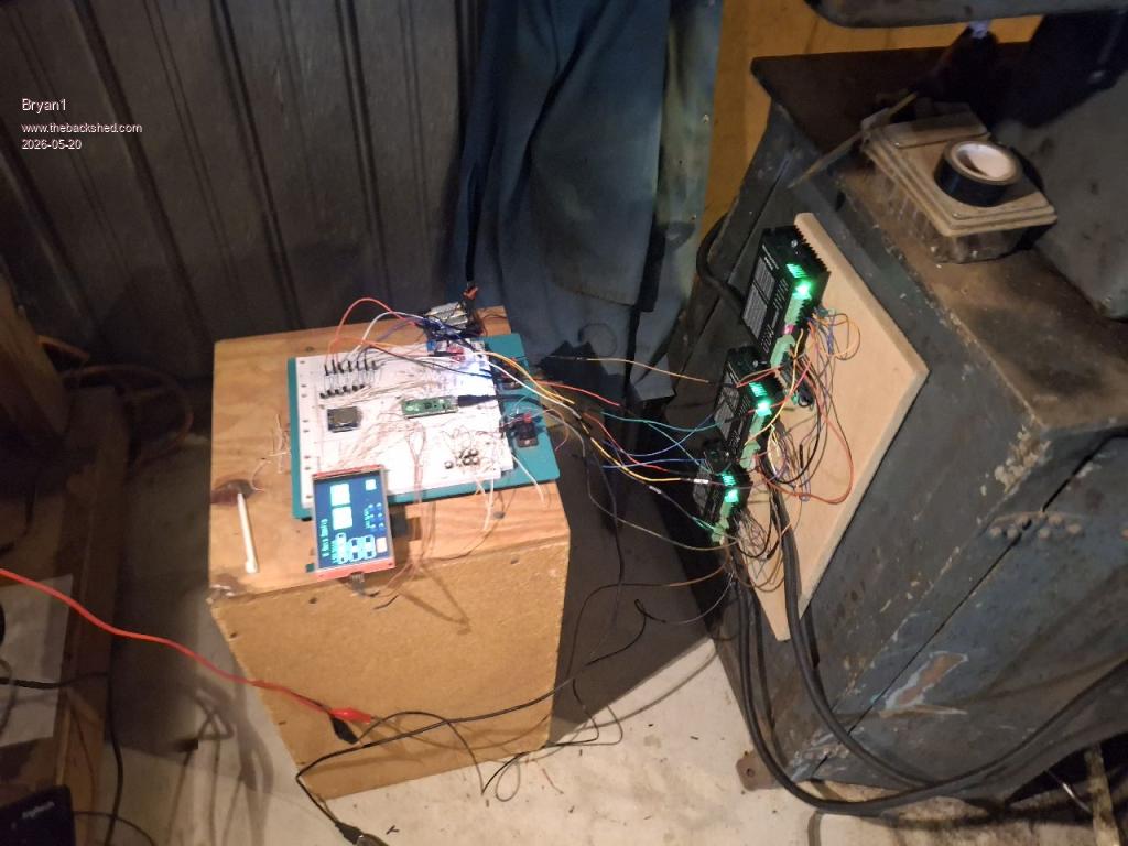 Lyle I do hope this makes your day mate got the X axis working on the grinder doing the calibration now and I did find putting the feedrate upto 1500 works a treatRegards Bryan Edited 2026-05-20 15:52 by Bryan1 |
||||
| Bryan1 Guru Joined: 22/02/2006 Location: AustraliaPosts: 2136 |
Now what I've found got the X axis moving and calibrating is fun but getting there but with the Y and Z axis got no movement at all with both axis. Both are in holding current mode too. Now when I jog the X axis the power supply does go just over an amp and with switch 4 off on all 3 DM556's the holding current is 0.567 amps, when I do to jog the Y and Z axis the power supply doesn't move at all so it doesn't look like they are working. I've checked all my wiring and nothing is out of place too |
||||
| Bryan1 Guru Joined: 22/02/2006 Location: AustraliaPosts: 2136 |
Well thats enough for oneday and a HUGE step forward with the X axis flying along now, I did find playing with different micro step modes and step counts on the X axis setup code it went from doing 8mm instead of 20mm to over 30mm with the same 20 Now using F900 got it moving nice and fast so a bit more tweaking in the morning should get the X axis sorted.With the Y and Z axis I'm going to check all the connections on the breadboard but nothing looked out of place. Now with playing with the code a few times the screen just did a white out where a USB reset was needed and also a few times while trying with the Y and Z axis the code did hang as going back and trying the X axis did nothing. So getting there Regards Bryan |
||||
| DaveJacko Senior Member Joined: 25/07/2019 Location: United KingdomPosts: 103 |
Thanks to Phenix and Mozzie.. my problem was I'm more used to GRBL, which is a bit Arduino-esque? you could call it a dialect of Gcode, ( which seems to have a few dialects, being from the '60's ) I didn't know that one needs a G1 before the Fnnn - that's the bit I missed thanks again, Dave Try swapping 2 and 3 over |
||||
| Bryan1 Guru Joined: 22/02/2006 Location: AustraliaPosts: 2136 |
Well finally got to start on this today and silly me had the 1K resistors out on the pico 2 pins so corrected it and turned it on. First tried the Y axis and it just moved smoothly so started on the Z xis where the next bit of fun is there to solve  With the play in the screw I'm going to put a thrust bearing under the flexible coupling as it does look like the coupling is fouling when it hits home. Now so far today about 6 or more white outs on the LCD and I found while playing with the DM556 when the stepper bogged the white out comes. Other times when Z wouldn't work going back to Y and X axis nothing with touch so the code hung, now I have setup the limits switch's and all work nicely so when a white out does happen I can stop the stepper code and the holding current does fall to mA when the E_Stop or a limit is pressed. So the fun continues Regards Bryan |
||||
| Bryan1 Guru Joined: 22/02/2006 Location: AustraliaPosts: 2136 |
Well had a few hours off as I was getting nowhere now just fired it all backup again and I'm finding with the Z axis the log+ and jog- are both going down and not eachway. Just reflashed the pico 2 with the code and it is still the same so not sure if this is a hardware or code fault. Anyway time to take the Z stepper motor and coupling off so I can get the Z travel wound up so it's close to the lower limit. |
||||
| mozzie Guru Joined: 15/06/2020 Location: AustraliaPosts: 400 |
G'day Bryan, Love the current setup, looks like a lot of things I have "in development" A couple of thoughts on the issue you are seeing: The stepper drivers output a LOT of RF noise on both the power input cables and the motor output cables if they are not screened. This might be getting into the breadboard LCD connections and causing grief. Perhaps try sticking an earthed metal tin / box / cover / baseplate around the breadboard and see if it changes anything. With multiple drivers being enabled together, there may be a momentary dip in the power rail, enough to upset the Pico / LCD. Try running with only the moving axis powered and see if it makes a difference. The coil winding machine is much smaller and the Pico / LCD are in an earthed aluminium housing but until I connected a short 2.5mm2 direct from the control box to the machine I still had problems with noise / dropouts / missed steps. There may also be a problem with your shed, I can see at least 2' square of bare concrete floor not something seen here in a while  Regards, Lyle. |
||||
| Bryan1 Guru Joined: 22/02/2006 Location: AustraliaPosts: 2136 |
Well I have got the Z axis moving nicely and got it close to calibration then without touching everything it went pair shaped where it looks like the Z axis the problem. It did feel a tad warm so got my infrared temp gauge and found the Z axis was 5 degrees hotter at 31C where the X and Y axis were both 26C with a 21C ambient. Now when I say pair shaped a few times when I've uploaded the voltage drops to 8.3 volts with the max 1.8 amps current. Now turn it off then turn it back on and it works and just when I'm close it seems I went too far where I needed to start from scratch. Now for final calibration I found getting the balance right between the steps in the code and microstep settings on the DM556. So my plan for the rest of the day is finishing off that pcb and just need to hook up the console pins and I want to design a lcd board so the SPI of both the lcd and SDCard can be brought out on a single connection. I do think by using the pcb will solve most of the teething so the quicker I get the order for the pcb's in the quicker this project can be. Regards Bryan Edit: yea mate cleaned up the corner and thought I would get a reaction Now Lyle once I get all the axis dialed in with the correct steps and micro step setting I will put my code up and also as we are using shared axis limits I did cut down the LED amount to 3 and just need to setup the interrupt for them. Edited 2026-05-21 17:05 by Bryan1 |
||||
| Bryan1 Guru Joined: 22/02/2006 Location: AustraliaPosts: 2136 |
OK got the pcb all finished and just uploaded the gerber to JLCPCB now man talk about breaking the bank $3.50 for 5 boards delivered in 7-10 days Then the fun can really start....... Regards Bryan |
||||
| matherp Guru Joined: 11/12/2012 Location: United KingdomPosts: 11604 |
Bryan Not to throw a damper but you are driving heavy machinery. |
||||
| Bryan1 Guru Joined: 22/02/2006 Location: AustraliaPosts: 2136 |
Too True Peter the macson surface grinder is one beast of a machine and I'm sure Lyle will agree it takes a lot of guts to use the said machine as more times than not the grinding wheel flies around the workshop in pieces and the part getting ground is stuck in the wall never to come out. So while getting each axis running, calibrated and all the limits in place until the Z axis can move up quickly in any misadventure where Lyle has said the Z axis may have be done in software as when a limit or E_stop is pressed the holding current falls to mA as I noticed today. Now after doing a Cnt-C in MCCC the stepper was still going and pushing a button I have to emulate a limit turns off the stepper mode in the pico 2. As the V.01 pcb is so cheap as Lyle said it will be going in a metal box to cut the interference the micro stepper cause. I'm sure by the time a grinding wheel is put on we may be several pcb's in as more things are thought of etc. Now once the resolution of the Z axis is known for putting a cut on may be a step or two and this will have to be done via software. Now silly me did forget to put the drill file in the zip and an email back back 1/2 an hour after I placed the order so a quick trip to my shed to export the drill file and add it to the zip fie was done. Got back down to the house where another email saying they received the updated zip and the pcb was now in production. Regards Bryan Edited 2026-05-21 19:05 by Bryan1 |
||||
| matherp Guru Joined: 11/12/2012 Location: United KingdomPosts: 11604 |
Bryan After Grogster's experiences please be careful of electrical interference spiking the PicoMite. Machine tools can be electrically very noisy. |
||||
| PhenixRising Guru Joined: 07/11/2023 Location: United KingdomPosts: 1988 |
Probably not a good time to discuss my BlueTooth E-Stop button, then. |
||||
| mozzie Guru Joined: 15/06/2020 Location: AustraliaPosts: 400 |
G'day Bryan, The limit switches are looked after by the stepper system, no need to monitor them directly, it can be done through PEEK(STEPPER STATUS) I hope you don't mind but I have had a bit of a session with the version of the software I last posted, have moved a few things around, added an E-Stop indicator, RESET switch and JOB RUN button, dropped the Limit indicators to 3 and programmed them to work. Also added some very basic graphics, although graphic design is NOT my strong point. Not sure whether to add a button to each axis setup page for the axis homing or put it all on its own page? any thoughts? These 4" LCD's are a great size, now to make a case.... Up to you if you want to use this or not, still a fair bit to do. SurGrind0005.zip Enough for one night, off to bed  Regards, Lyle. |
||||
| Mixtel90 Guru Joined: 05/10/2019 Location: United KingdomPosts: 8937 |
I sincerely hope that, at the very least, a normally closed ESTOP loop kills everything stone dead immediately and won't let the machine have it's motor power back until everything has been made safe manually. Ideally it should happen if the first of two very close limit switches (in all directions) fails too. Mick Zilog Inside! nascom.info for Nascom & Gemini Preliminary MMBasic docs & my PCB designs |
||||
| The Back Shed's forum code is written, and hosted, in Australia. | © JAQ Software 2026 |
