
|
|
Forum Index : Microcontroller and PC projects : Armmite F4: programming the firmware
| Author | Message | ||||
| lizby Guru Joined: 17/05/2016 Location: United StatesPosts: 3833 |
You're probably aware of this thread concerning this module. I successfully flashed F4 mmbasic to the 1MB version of this module, the STM32F407VGT6. I successfully did limited testing, but then had an error which caused me to reflash, and I was subsequently unable to get the mmbasic console prompt back. I did not spend much time on it. Hope you have better luck. It looks like a useful module to me, somewhat smaller than the F4 we have been using. If successful, I hope you will be able to share your source changes (if not the firmware because of Geoff and Peter's reasonable concerns), and especially your compilation process. PicoMite, Armmite F4, SensorKits, MMBasic Hardware, Games, etc. on FOTS |
||||
| CaptainBoing Guru Joined: 07/09/2016 Location: United KingdomPosts: 2171 |
have I missed something? I searched the forum but there seems no mention to what I found with my F4 setup today... the Program does not appear to be stored in Flash. Any program is lost when you take out the CR1220. Had one that kept losing the program, checked the coin cell, 0.6V, changed out for a nice fresh one, all is well. Not a problem in itself, more a note to self that if the beast is used in anger, you need to (carefully) change the coin cell with it powered up. There are a number of bespoke F4 designs appearing, what's the arrangement there? > memory Flash: <-------- This + 14K (10%) Program (513 lines) <-------- this = Lies(?) 118K (90%) Free RAM: 5K ( 4%) 19 Variables 0K ( 0%) General 109K (96%) Free > |
||||
| matherp Guru Joined: 11/12/2012 Location: United KingdomPosts: 11673 |
It is, but when you remove the battery the options are lost. The firmware understands this as a corruption and re-initialises everything (think OPTION RESET + NEW) |
||||
| CaptainBoing Guru Joined: 07/09/2016 Location: United KingdomPosts: 2171 |
understood - thanks |
||||
| morgs67 Regular Member Joined: 10/07/2019 Location: AustraliaPosts: 78 |
This severely limits the use of the F4. If I make something for a friend, the first time there is a battery failure it's a return to maker for reprogramming. Is there anyway of storing options in flash so that the F4 recovers with a warning/lost time etc? |
||||
| morgs67 Regular Member Joined: 10/07/2019 Location: AustraliaPosts: 78 |
double Edited 2021-05-05 10:44 by morgs67 |
||||
| lizby Guru Joined: 17/05/2016 Location: United StatesPosts: 3833 |
This just bit me. I couldn't figure out why my F4 set to OPTION LCDPANEL IPS_4_16, L kept reverting to the default whenever I unplugged it for more than a few seconds. Battery tests at .09V! I've replaced it, and will see how it goes. I'm not sure how soon I'd have figured out if I hadn't remembered this post. PicoMite, Armmite F4, SensorKits, MMBasic Hardware, Games, etc. on FOTS |
||||
| CaptainBoing Guru Joined: 07/09/2016 Location: United KingdomPosts: 2171 |
I have an F4 going in a piece of kit. I don'tknow why the above happens but I have to mitigate losing the settings when the coin cell would be replaced. On the back of it, I have removed the cell and lashed up some wires out to a 2xAAA holder (+some other bits n bobs) somewhere it can easily be got at. Spare A/D pin monitors battery voltage through a p/d to give warning when the battery needs sorting. a Pain but not insurmountable. Instructions are to replace batteries with power on. With AAAs I reckon it will be years but at least now I should get it done without losing the settings and I get ample warning of the battery getting low. |
||||
| Mixtel90 Guru Joined: 05/10/2019 Location: United KingdomPosts: 8981 |
As the battery voltage can be checked in software using PIN(BAT) at least we can flag a warning to change the battery before it gets too low and we lose the options, I suppose... Mick Zilog Inside! nascom.info for Nascom & Gemini Preliminary MMBasic docs & my PCB designs |
||||
| CaptainBoing Guru Joined: 07/09/2016 Location: United KingdomPosts: 2171 |
! did not know that. will play Thanks for the tip EDIT: > ? pin(bat) 3.092893773 Oh yeah! nice, saved a pin - cheers. Guess I need to read the manual a bit more Edited 2021-05-11 20:41 by CaptainBoing |
||||
| lizby Guru Joined: 17/05/2016 Location: United StatesPosts: 3833 |
Very good info here. This raises the question: at what level of ?pin(bat) should the battery be changed? I got this with a fresh battery: > ?pin(bat) 3.76981685 ~ Edited 2021-05-11 23:55 by lizby PicoMite, Armmite F4, SensorKits, MMBasic Hardware, Games, etc. on FOTS |
||||
| CaptainBoing Guru Joined: 07/09/2016 Location: United KingdomPosts: 2171 |
yep agree. datasheet says: "VBAT = 1.65 to 3.6 V: power supply for RTC, external clock 32 kHz oscillator" worst case IVBat is given as 11uA (but typically half that). I am going for 1.8V as my threshold. VBAT does arrive through a diode (one half of a BAT54C) but measuring that; the voltage drop seems to only be about 90mV with power off, so I think the PIN() voltage is going to be accurate enough. My concern here is that when switched on, one may not be able to accurately sense VBAT when it dips below VCC. I may end up using an AD pin after all. In my case I have removed the cell holder and wired it to a holder for a couple of AAAs. If they get to a volt each they are pretty much finished. I will write a section of code on a long timer to check the battery voltage and complain when it gets to the limit. Assuming the typical alkaline AAA is around 1000mAh. I should get about 6 years on a pair before the software starts to cry - and that is if it's off the whole time. I have the 3V from the batteries coming through a 3K3 resistor to a 3V3 Zener just in case the batteries are a bit "strong". A fresh AAA is about 1.6V+ so the Zener probably overkill but I'd rather that than a fried processor. A 1000uF cap across the Zener holds the power from 2V to 1.65V up for about 35 seconds (into 180K load which is 11uA - worst case) so plenty of time to swap the AAAs out. Edited 2021-05-12 16:14 by CaptainBoing |
||||
TassyJim Guru Joined: 07/08/2011 Location: AustraliaPosts: 6550 |
Lithium coin batteries discharge rather rapidly once they get below 2.5V so I would use somewhere near there as a cutoff. https://data.energizer.com/pdfs/lithiumcoin_appman.pdf CR1220: https://data.energizer.com/PDFs/cr1220.pdf 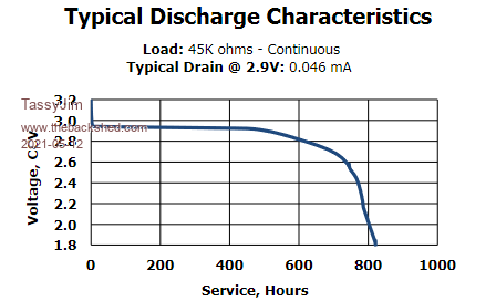 Jim VK7JH MMedit |
||||
| Mixtel90 Guru Joined: 05/10/2019 Location: United KingdomPosts: 8981 |
I looked at that graph and panicked. Then realised that it's for 46uA and we're more likely to b closer to 4.6uA. :) Phew! Edited 2021-05-12 07:57 by Mixtel90 Mick Zilog Inside! nascom.info for Nascom & Gemini Preliminary MMBasic docs & my PCB designs |
||||
disco4now Guru Joined: 18/12/2014 Location: AustraliaPosts: 1134 |
I am thinking that VBAT is reading the lower of battery voltage and VIN as they both are connected via the BAT diode,maybe it does need to be read via an external pin. I know you still get a reading with the coin cell removed when it powered up. F4 H7FotSF4xGT |
||||
| phil99 Guru Joined: 11/02/2018 Location: AustraliaPosts: 3327 |
When reading PIN(BAT) some averaging is needed. Also the first reading after a startup is usually a bit higher than the rest on my F4. > for n= 1 to 20 : ? pin(bat) : next 3.257289377 3.128351648 3.133186813 3.118681319 3.126739927 3.12996337 3.112234432 3.125128205 3.118681319 3.133186813 3.138021978 3.131575092 3.128351648 3.128351648 3.133186813 3.128351648 3.118681319 3.12996337 3.118681319 3.118681319 > |
||||
| TassyJim Guru Joined: 07/08/2011 Location: AustraliaPosts: 6550 |
More like 2uA 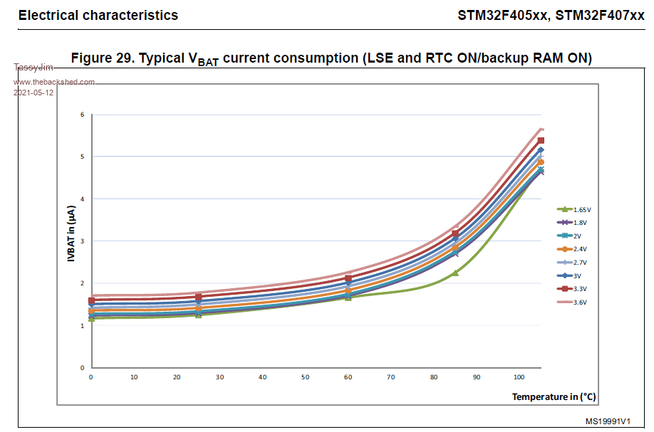 The F4 board does have a diode pair combining 3.3V with the battery so I assume that Vbat will be the higher of the two (less volt drop). The H7 boards have jumpers so Vbat readings will make sense. Even if the F4 board spends most of the time shut down, a good CR1220 will last a few years. Jim VK7JH MMedit |
||||
| Mixtel90 Guru Joined: 05/10/2019 Location: United KingdomPosts: 8981 |
It would be interesting to isolate the 3.3v feed to the diode (Q1) and take it from a digital output instead. Then, under normal conditions, keep that output high to power the clock. To test the battery turn the output off and read the pin. The track is visible on top, right next to the Q1 silkscreen. Mick Zilog Inside! nascom.info for Nascom & Gemini Preliminary MMBasic docs & my PCB designs |
||||
| dMajo Newbie Joined: 18/05/2020 Location: ItalyPosts: 29 |
Nice idea 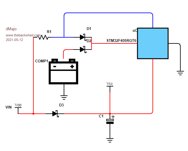 and going a bit further you can use an interrupt capable DIO. When set as input you can monitor power supply loss and eg save application parameters (otherwise stored in RAM) while the capacitor backup lasts. When configuring the DIO as output and driving it low you can measure the battery voltage. ALLdataEE.com EDU Promos |
||||
| Mixtel90 Guru Joined: 05/10/2019 Location: United KingdomPosts: 8981 |
That's a neat idea too... :) Mick Zilog Inside! nascom.info for Nascom & Gemini Preliminary MMBasic docs & my PCB designs |
||||
| The Back Shed's forum code is written, and hosted, in Australia. | © JAQ Software 2026 |
