
|
|
Forum Index : Microcontroller and PC projects : Stepper Project
| Author | Message | ||||
| phil99 Guru Joined: 11/02/2018 Location: AustraliaPosts: 3316 |
From what they have written the catch with this machine is every thing except the Z-axis must stop. The Z-axis must raise the grinder off the work as fast as possible to prevent a rapid redistribution of the grinding wheel and workpiece. On the matter of shielding the wiring and Pico, the electromagnetic work clamp will be radiating a strong 50Hz field. If there is more than one earth point on the shielding circulating currents could increase interference. |
||||
Bryan1 Guru Joined: 22/02/2006 Location: AustraliaPosts: 2136 |
Phill the magnetic table I have is an old Eclipse one where a handle engages the magnet so no electromagnetic interference here at all from the magnetic table. Got a few loads of mulch to do this morning so it will be after lunch before I can test this new code which I am looking forward too  Now to throw a cat among the pigeons since I bought that 4" LCD Elecrow keep sending me emails with their products and the email I got this morning would be the ducks nuts if it could work with MMBasic as a 10" HDMI touch screen would fit the bill for a professional finish. But as usual you guy's will say "Your Dreaming Son so go polish my towbar" Regards Bryan |
||||
| phil99 Guru Joined: 11/02/2018 Location: AustraliaPosts: 3316 |
Ok I see it now in the photo on page 4. "Eclipse permanent magnet chuck". |
||||
| Bryan1 Guru Joined: 22/02/2006 Location: AustraliaPosts: 2136 |
Now my surface grinder does sit on a steel cupboard where the top is a 3/8" plate and the cupboard is an angle iron frame with sheet metal siding. The DM556's are mounted on some 16mm MDF and a 1mm gal plate box will be made to enclose the setup to shield the setup from foreign matter. I am thinking of mounting the pico 2 board inside the cupboard in a 1mm gal plate box I'll make so shielding should be taken care of. Checked JLCPCB this morning and my PCB is now in Production so won't be long before it arrives. Now Lyle if you could PM me your address as soon as I get these boards I will send you a couple over so you can have a play with them.Regards Bryan |
||||
| vegipete Guru Joined: 29/01/2013 Location: CanadaPosts: 1182 |
Do you think you could actually lift the wheel any where near fast enough to prevent destruction? I seriously doubt it. You're talking SawStop like speeds, with much higher rotating mass and translating (lifting) mass. Workpiece is off into the wall, wheel chunks are spreading. Ouchies. Visit Vegipete's *Mite Library for cool programs. |
||||
| mozzie Guru Joined: 15/06/2020 Location: AustraliaPosts: 400 |
G'day All, The issue with the surface grinder is mainly due to the inertia of the grinding wheel and spindle. If you hit the E-Stop and let the wheel spin down in contact with the job, at some point in its ramp down it will stop grinding and grip, depending on the speed it is doing it will either: STOP - this is the best outcome - maybe no damage. Launch the job off the magnetic clamp into space / wall etc Tip the job on the table, either stopping / chipping / destroying the wheel and job Try to stop in a hurry - due to the inertia of the motor and spindle this can undo the spindle nut sending the grinding wheel on an adventure of its own and the speed its doing when it releases dictated how far it goes, sometimes a long way  EDIT: My mistake, this happened when the spindle bearing failed and locked solid. The fact you are normally standing in front of it when one of these things happens can be very "exciting" We only really need to lift the wheel a couple of mm to clear the job on an E-Stop but sometimes the higher the better. When setup and operating / operated correctly they are an invaluable piece of equipment, they are, however, VERY unforgiving if not. Regards, Lyle. Edited 2026-05-22 14:23 by mozzie |
||||
| Bryan1 Guru Joined: 22/02/2006 Location: AustraliaPosts: 2136 |
Well still no luck getting to this project after doing the mulch this morning where I moved my mini excavator found why I had a oil trail and the hydraulic oil tank emptied out  The hydraulic hose connection was loose on the left track drive motor and I hit a submerged rock with it which much of given enough slack on the loose connection to expel the hydraulic fluid. So as I have about 50 litres of hydraulic oil time to setup a decanter hose and as I have so many tools down there may aswell use my forrester as carrying a 20 litre drum oil oil up down the hill isn't a option. The hydraulic hose connection was loose on the left track drive motor and I hit a submerged rock with it which much of given enough slack on the loose connection to expel the hydraulic fluid. So as I have about 50 litres of hydraulic oil time to setup a decanter hose and as I have so many tools down there may aswell use my forrester as carrying a 20 litre drum oil oil up down the hill isn't a option.Now Lyle why I'm thinking about this Z axis for generally moving up and down to set the job we can still use the stepper system. Then we want to set the job to run the Z axis is turned off which may require a 4th DM556 so the Z axis code can be run in software. Now we could sacrifice GP0 to switch a transistor circuit to turn one DM556 off and the other on so the software DM556 can run the Z axis. |
||||
| Mixtel90 Guru Joined: 05/10/2019 Location: United KingdomPosts: 8937 |
STOP and ESTOP are entirely different. Under an ESTOP condition one or more lives are at stake so it doesn't matter if the machine mangles itself and dies terminally. The grinding motor windings should, ideally, be injected with DC directly into them (not via fuses) or at least short circuited if there's no failsafe brake on it as it has to stop as quickly as possible. The motor fuses are expendable. It doesn't matter if a coupling shears - having a shear pin might be a good idea anyway. Likewise you can't assume that the Z axis actuator can, never mind will, move. The electronics might be on fire. The workpiece is dead anyway. You can't rely on any electronic control being available as there's a possibility that it's a fault somewhere in there that's made an ESTOP necessary. Basically, there's no requirement for the machine to be recoverable from ESTOP. You can't test the ESTOP system under full danger conditions, obviously, but it has to work correctly the first, and quite possibly the only, time. STOP would, of course, lift the grinding wheel from the workpiece before stopping it in the normal way. You would prefer the machine to stay in one piece and the workpiece to be usable. :) Mick Zilog Inside! nascom.info for Nascom & Gemini Preliminary MMBasic docs & my PCB designs |
||||
| Bryan1 Guru Joined: 22/02/2006 Location: AustraliaPosts: 2136 |
Look Guy's this is like my inverter project where it took a year or two to get going and it just works. So this Macson Surface Grinder has started as Lyle said he had the same machine, now where my attempt was actually making 5 page GUI code where Lyle got it work for me. Just got an email the boards are done so they will be here next week and by making the box to shield the RF I am thinking the DM556's may be better in the steel cupboard to cancel out the RF. Now as this whole project went for a 2350A I am thinking as we ran out out in/outs on the 2350A Peters B big board may be the way to go so a bigger lcd screen can be used and do need to use external inputs so we can do the 6 limits so one can know which limit was done. Now Mixtel, Peter and everyone else before this project goes live a grinding won't go on and I am wondering with the stepper code can an option with the step code for each axis but for the Z axis can have an option where instead of distance steps are made, now now this could be an option to put on the Z axis G_Axis Regards Bryan |
||||
| PhenixRising Guru Joined: 07/11/2023 Location: United KingdomPosts: 1988 |
Dunno. In the case of a grinder, that's bit like pulling the trigger on a firearm and then putting the safety on. If the wheel shatters or bites into the workpiece, it's pretty much all she wrote. In this particular case, good ol' guarding. |
||||
| mozzie Guru Joined: 15/06/2020 Location: AustraliaPosts: 400 |
G'day, Coming from the mobile plant and trucking industry but having trained as a mains sparky the whole E-Stop issue has always been a PITA, good thing this is going in my shed and will be used by me, so will be fitted accordingly. As Phenix points out, a good guard and not having to physically operate the machine makes it far safer already. Bryan, many thanks for the offer on the board, PM on the way shortly. Also had a bit of a chuckle today, dug my way into what I though was the big surface grinder similar to Bryans only to find a press hiding under the tarp  So now I'll be automating the smaller one I use most of the time anyway Regards, Lyle. |
||||
| vegipete Guru Joined: 29/01/2013 Location: CanadaPosts: 1182 |
I haven't used surface grinders often, thus I've never had the brown pants moment when things go awry. I am looking at a job in the next few days of a 21 inch long piece on a grinder with perhaps 21 1/8 inch travel. The automatic hydraulics have packed it in, so it will be an entirely hand cranked affair. The machine is near a huge plate glass window - let's hope it stays in one piece.  Visit Vegipete's *Mite Library for cool programs. |
||||
| mozzie Guru Joined: 15/06/2020 Location: AustraliaPosts: 400 |
G'day, Don't want to take over Bryans thread, but now I've finally realised the old surface grinder is no longer here I should post some pics of the unit to be automated. 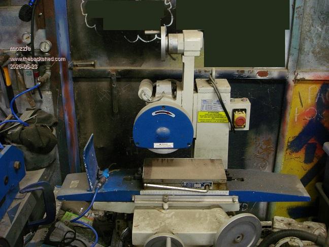 And this is the carriage drive out of the old surface grinder, there are two cone clutches between the bevel gears that operated the carriage left and right, and then a ratchet mechanism moved the table across the grinding wheel. Aren't we lucky we now can do this with stepper motors instead  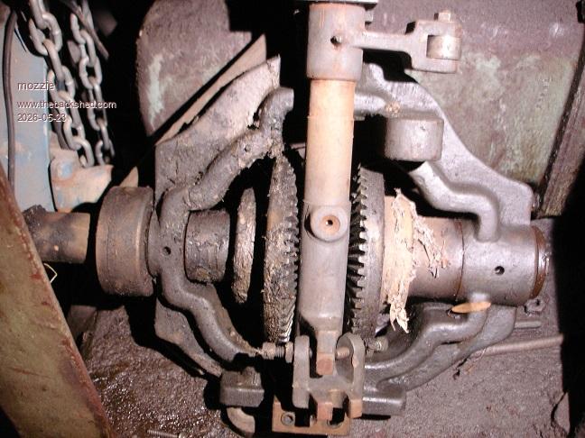 The spindle motor is around here somewhere as well, I think thats all thats left. Vegipete, that's quite a big job, do you mind me asking what it is? I guess diesel engine heads are ground and some of them are huge. Regards, Lyle. |
||||
| PhenixRising Guru Joined: 07/11/2023 Location: United KingdomPosts: 1988 |
Automatic hydraulics as in proportional valves and encoders? Picomite can now handle that, no sweat |
||||
| mozzie Guru Joined: 15/06/2020 Location: AustraliaPosts: 400 |
G'day Bryan, I am pretty sure there is enough I/O on the PICO to make it all work, the SERIAL CONSOLE was just an idea so really those 2 pins could be used for the Z-Axis enable outside the stepper system. If you are happy with the 4" LCD a rework of the pages might make some things easier to read. With a bit of luck we can use the Z-Axis in the stepper routine for homing and then remove it for running, otherwise it'll be done completely from mmbasic. More testing to follow. A little more research into this small surface grinder just for info: Machine is calibrated in Metric but uses Imperial leadscrews and gears. Z axis is 0.1" pitch leadscrew geared at 2:1 so 0.05"(1.27mm) per rev, with a stepper tuned to 800 steps/rev we get 0.0625/1000" per step. I think this should be small enough. X axis is 1/4" pitch rack and 26 tooth pinion so 6.5" per turn and approx 13" travel, 2 turns end to end. Y axis is 0.1" pitch leadscrew Looking at toothed belt drive on all 3 so I can leave the handwheels in place. Just gotta finish another couple of 1000 things before this can start... Regards, Lyle. |
||||
| mozzie Guru Joined: 15/06/2020 Location: AustraliaPosts: 400 |
Hi, And a couple more of the coil winder machine I have mentioned a few times. First version mechanical coil winder: 3phase motor and 90:1 gearbox, Landrover S2 transfer case + Rover V8 timing chain, M30 allthread 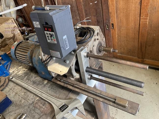 New MMBasic Stepper coil winder: Y-Axis off CNC machine, Overhung load adaptor for hydraulic motor, modified S2 Landrover output shaft, gears from photocopier 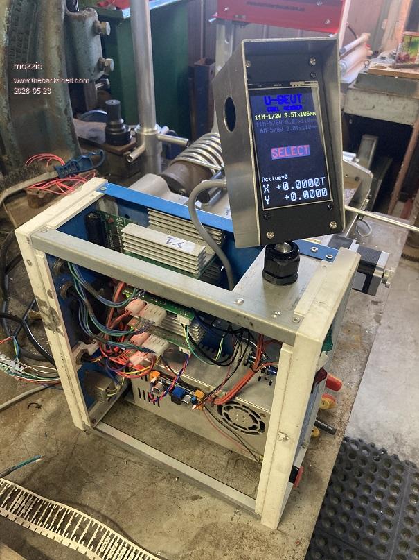 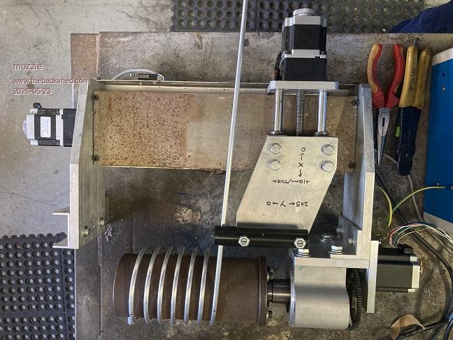 And my favourite machine, maybe PicoMite CNC one day: 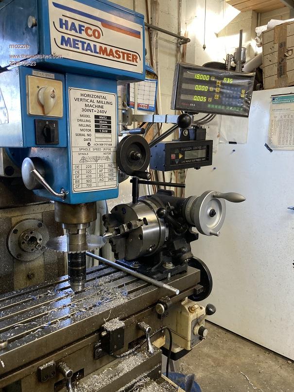 And even some freshly swept concrete on show, very rare indeed  Regards, Lyle. |
||||
| mozzie Guru Joined: 15/06/2020 Location: AustraliaPosts: 400 |
G'day Bryan, Tried to PM but your inbox is full. Hope the hydraulic repairs are proceeding well nothing like the smell of burnt hydraulic oil as it runs down your arm into your shirt sleeve, oh the joy Regards, Lyle. |
||||
| Bryan1 Guru Joined: 22/02/2006 Location: AustraliaPosts: 2136 |
Lyle I deleted a heap of messages so you should be able to send one now anyway got an email today saying the pcb's have shipped |
||||
| Bryan1 Guru Joined: 22/02/2006 Location: AustraliaPosts: 2136 |
Just had a play in sprint layout and designed up the LCD Board Got it fitting on a 50x50mm pcb so the cost maybe even cheaper Anyway the connector on the left is for the LCD, the one in the centre for the SD_Card and the one on the right is the PCB connector so hopefully I got all the connections right and as usual the experts will find something wrong 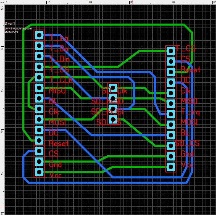 Regards Bryan Edited 2026-05-24 11:52 by Bryan1 |
||||
| Bryan1 Guru Joined: 22/02/2006 Location: AustraliaPosts: 2136 |
Now Lyle I did put the 05 code on the pico 2 and gave it a run and all 3 axis did move nice and quietly, now those arrows which you put in didn't do anything and I kept getting white outs on the lcd so may just wait until the boards get here so solid connections can be had for the LCD. I want to get that LCD board off to JLCPCB by tomorrow so they can be here a few days after the pico 2 stepper boards are here. |
||||
| The Back Shed's forum code is written, and hosted, in Australia. | © JAQ Software 2026 |
